Archive 4584NP
Autoloader DDS-DC (Rev 1.7.1)
 
Specification
| Data Transfer |
Sustained |
366 Kbytes/s (1:1 base) |
| 732 Kbytes/s (2:1 typical) |
| 1464 Kbytes/s (4:1 max) |
| Nominal Capacity |
60-metre cartridge |
1.3 Gbyte (1:1 base) |
| 2.6 Gbyte (2:1 typical) |
| 5.2 Gbyte (4:1 max) |
| 90-metre cartridge |
2.0 Gbyte (1:1 base) |
| 4.0 Gbyte (2:1 typical) |
| 8.0 Gbyte (4:1 max) |
| Unrecoverable Errors |
Less than 1 in 1015 data bits |
| Recording Format |
ANSI/ECMA Digital Storage with Data
Compression (DDS-DC) |
Media (ten) |
1.3GB DDS tape |
DA44990 |
Using the Drive
Front Panel
The front panel of the Autoloading DDS-DC drive includes a eight
character display, four LEDs and two buttons. The front panel is illustrated below.
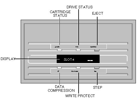
Front Panel Display
The front panel display is used to display eight alphanumeric characters
indicating the status of the drive. If the drive is installed with the display horizontal,
text is oriented to read from left to right. If the drive is installed with the display
vertical, text is oriented to read from top to bottom.
Warning
When the drive drawer is closed and a magazine present the display
identifies the magazine slot that is positioned for use. the drive drawer is closed
without a magazine present no message is displayed. When the drawer is open and a other
magazine than a four cartridge magazine is present, the drive identifies the magazine and
it locks it and the drawer in place. display The indicates which slot is positioned for
use. If the slot positioned for use does not contain a cartridge the display flashes
rapidly. If the slot contains a correctly inserted cartridge the display flashes slowly
identifying the slot. The slow flash continues for five seconds after the magazine is
stepped using the STEP button. Once the cartridge is loaded the slot number is displayed
continuously. If a cartridge is not correctly inserted in the magazine the display shows
the CHECK MAGAZINE message. Whenever the drive needs operator intervention the display
flashes OPERATOR.
Warning
It is vital that the text reads left to right when the display is
horizontal, and top to bottom when the display is vertical. The drive must not be operated
with the text incorrectly oriented.
If text is displayed incorrectly, open the drive drawer, eject the
magazine, power the system down and refer to Drawer switches for information on changing
the orientation.
Messages that the drive can display
| Message |
Meaning |
| MAG ERR |
Magazine is jammed |
| ILLEGAL |
Button has no function |
| NO CASS |
A cartridge is no present |
| CASS IN |
A cartridge is in the drive |
| CLEANING |
Cleaning cycle is occurring |
| OPERATOR |
Operator action is required |
| EJECTING |
Cartridge is being ejected |
| INSERT |
Cartridge is being inserted |
| SCAN MAG |
Magazine is being initialised |
| DISMOUNT |
Magazine is being dismounted |
| SLOT-nn |
Slot number nn is in position |
| OPENING |
Drawer is opening |
| CLOSING |
Drawer is closing |
| CHK MAG |
The cartridge is not correctly |
| |
inserted in the magazine |
Front Panel Buttons
EJECT Button
The EJECT button ejects the currently loaded cartridge and , if a
magazine is being used, dismounts the magazine, opening the drawer if necessary.
STEP Button
This button allows you to step through the cartridges in the magazine in
turn, until you reach the one you require.
Pressing the STEP button returns the current cartridge to the
magazine and moves the magazine to the next cartridge. If a cartridge is present in that
slot it is loaded into the drive after a five second delay.
The delay allows you to step the magazine to the next cartridge if
the current one is not the one you require.
When the magazine is stepped beyond the last slot it moves back to the
first slot.
Front Panel LEDs
| LED |
Action |
Meaning |
| Drive Status |
ON |
The drive is reading or writing the cartridge. |
| Flashing rapidly |
A hardware fault has occurred, or dew has been
detected. |
| Cartridge Status |
ON |
A cartridge is in the drive and is not generating
excess errors. |
| Flashing slowly |
A cartridge is in the drive and is generating excess
errors (Warning). Use a cleaning cartridge to clean the heads. |
| Flashing slowly (with drive status LED flashing) |
A pre-recorded audio cartridge is in the drive. |
| Flashing rapidly |
The drive cannot write to the tape (Error). Use a
cleaning cartridge to clean the heads. |
| Data compression |
ON |
A data compression or decompression operation is in
progress. |
| Write protect |
ON |
The cartridge in the drive is write protected. |
Write-protecting a cartridge
A cartridge can be write-protected by sliding the white tab on the
cartridge so that the recess is revealed. In this position, data can be read from the tape
but not written to it.
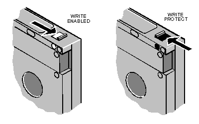
Magazine operation
Loading cartridges
To load cartridges hold the magazine with the flat side towards you, so
that the cartridge slots face away from you. Then insert a cartridge with the write
protect tab facing you at the right end of the cartridge.
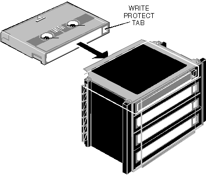
The cartridge should seat firmly in the slot. Repeat the process for the
remaining cartridges.
Inserting a magazine
The drive senses when a four cartridge magazine is used, and
automatically closes the drawer and loads the first (top) cartridge. To load a four
cartridge magazine:
1, Press the EJECT button to open the drawer. The drawer will open
and the display will indicate that operator action is required.
2, Align the loaded magazine over the open drawer with the flat
side of the magazine towards you, and the protrusions on the sides of the magazine
matching the cut-outs in the drawer.
3, Place the magazine gently in the drawer. Do not force it. The
drive senses its presence, positions it and closes the drawer automatically.
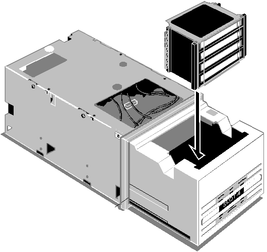
Using a single cartridge
The drive can be operated with a single cartridge. To load a single
cartridge:
1, Press the EJECT button to open the drawer. The drawer will open
and the display will indicate that operator action is required.
2, Insert the cartridge into the slot as shown in the following
illustration, with the write protect tab facing you at the right end of the cartridge.
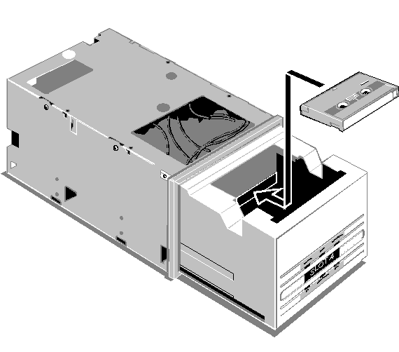
3, Gently push the cartridge into the drive until the drive pulls the
cartridge into the opening.
Once the cartridge is in the drive you may close the drawer if you wish.
Cleaning the drive
Head cleaning
There are two points at which the drive heads should be cleaned.
1, As routine maintenance after every 25 hours of read/write activity.
2, Whenever the cartridge status LED flashes.
Note
To clean the heads insert a cleaning cartridge. These are available from
Apricot (GH46865).
Note
The drive automatically recognises the cleaning cartridge, loads it and
runs it for approximately 10 seconds, before it is ejected. Each time the cleaning
cartridge is used a clean unused portion of the tape is advanced. After approximately 30
uses the entire tape is used and a new cartridge is required.
Note
The flashing of the cartridge status LED could refer to a damaged tape,
or a tape nearing the end of its life. If cleaning the heads does not correct the flashing
LED condition, replace the tape.
Note
Do not use an audio DAT cleaning cartridge, the drive will not recognise
it as a cleaning cartridge.
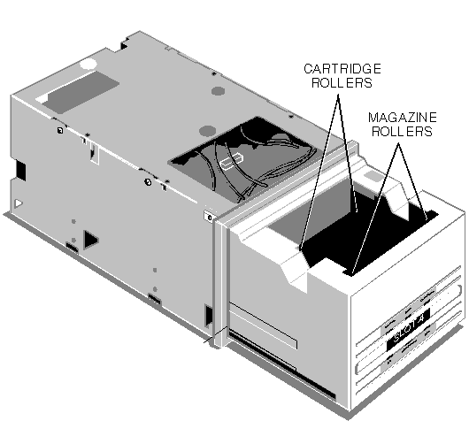
Cleaning the cartridge rollers
To clean the cartridge rollers:
1. Press the EJECT button and, once the drawer is open, remove the
magazine or cartridge.
2. Dip one end of a cotton swab in ethyl alcohol.
3. Press the STEP button three times within three seconds. CLEAN 1 will
appear on the display, and the cartridge rollers will rotate for 10 seconds.
4. As the cartridge rollers begin to rotate extend the swab into the
drawer and wipe the rollers with the wet end of the swab.
5. While the rollers are still rotating wipe them with the dry end of a
cotton swab.
Cleaning the magazine rollers
Cleaning the left magazine rollers
To clean the left magazine rollers:
1. Press the EJECT button and, once the drawer is open, remove the
magazine or cartridge.
2. Dip one end of a cotton swab in ethyl alcohol.
3. Press the STEP button three times within three seconds. CLEAN 2 will
appear on the display, and the left magazine rollers will rotate for 10 seconds.
4. As the left magazine rollers begin to rotate extend the swab into the
drawer and wipe the rollers with the wet end of the swab.
5. While the rollers are still rotating wipe them with the dry end of a
cotton swab.
Cleaning the right magazine rollers
To clean the right magazine rollers:
1. Press the EJECT button and, once the drawer is open, remove the
magazine or cartridge.
2. Dip one end of cotton swab in ethyl alcohol.
3. Press the STEP button three times within three seconds. CLEAN 3 will
appear on the display, and the right magazine rollers will rotate for 10 seconds.
4. As the right magazine rollers begin to rotate extend the swab into
the drawer and wipe the rollers with the wet end of the swab.
5. While the rollers are still rotating wipe them with the dry end of a
cotton swab.
Display cleaning
If necessary the front panel display can be cleaned with a damp cloth
and soapy water.
Warning
Do not use detergents or any proprietary cleaning solutions. These may
damage the display.
 
Environment
| Power |
Voltage |
+12Vdc ± 10% |
| +5Vdc ± 7% |
| Ripple |
+12V: 100mV pk-pk |
| +5V : 50mV pk-pk |
| Current (max) |
3.7A @ + 12V |
| 2.2A @ + 5V |
 
Drive Configuration
Drawer switches
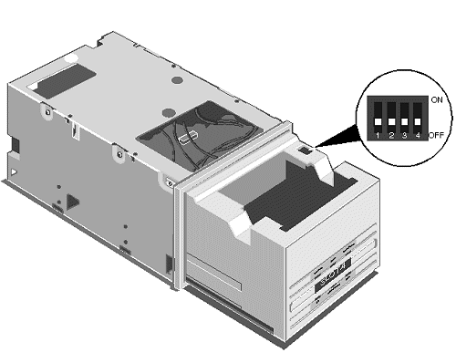
Switch 1
Switch 1 determines the orientation of the characters on the display.
When switch 1 is off the display reads from left to right, when switch1 is on the display
reads from top to bottom.
It is vital that switch 1 is set in the correct position, in addition to
the display orientation the position of this switch also changes the operation of the
drive mechanism.
Switch 2
Switch 2 determines whether the first cartridge in the magazine is
automatically loaded into the drive. When switch 2 is off the cartridge is not loaded,
when switch 2 is on the cartridge is loaded.
Top panel switches
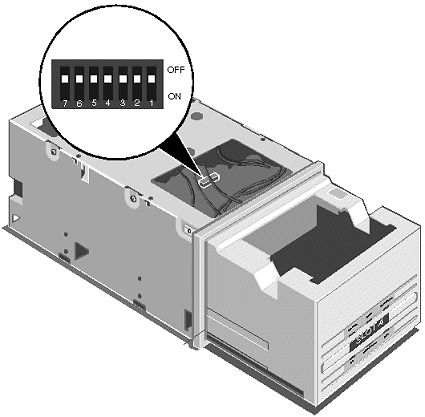
With the drive out of the system a bank of seven switches is available
on the circuit board at the top of the drive. The location of the switches can be seen in
the illustration.
Switch |
Function |
1 |
Display language |
2 |
Display language |
3 |
Continuous cycle |
4 |
Display intensity |
5 |
Power on self test |
6 |
Reserved |
7 |
Reserved |
Switches 1 and 2
These two switches determine the language used by the display as
follows.
Switch |
Language |
2 |
1 |
|
OFF |
OFF |
English |
OFF |
ON |
French |
ON |
OFF |
German |
ON |
ON |
Spanish |
Switch 3
Switch 3 determines the action of the drive after it accesses the last
cartridge in the magazine. When switch 3 is off the drive stops. When switch 3 is on the
drive returns to the first cartridge.
Switch 4
Switch 4 controls the intensity of the display. When switch 4 is off
display intensity is normal. When switch 4 is on display intensity is high.
Switch 5
Switch 5 controls whether the drive runs its self test sequence on power
up. When switch 5 is off the drive does not run the self test sequence. When switch 5 in
on the drive does run the self test sequence.
Rear panel switches
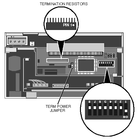
With the drive out of the system a bank of eight switches is available
on the circuit board at the rear of the drive. The location of the switches is indicated
in the illustration below.
The functions of these switches are given in the following table.
Switch |
Function |
1 |
SCSI ID bit 0 |
2 |
SCSI ID bit 1 |
3 |
SCSI ID bit2 |
4 |
SCSI mode |
5 |
Parity |
6 |
DDS pass through |
7 |
Reserved |
8 |
Power on self test |
Switch 1, 2 and 3
These three switches determine the identity of the drive on the SCSI
bus.
Switch |
Identity |
3 |
2 |
1 |
|
OFF |
OFF |
OFF |
0 |
OFF |
OFF |
ON |
1 |
OFF |
ON |
OFF |
2 |
OFF |
ON |
ON |
3 |
ON |
OFF |
OFF |
4 |
ON |
OFF |
ON |
5 |
ON |
ON |
OFF |
6 |
ON |
ON |
ON |
7 |
In Apricot system it is recommended that tape drives use
SCSI identity 2.
Switch 4
This switch is used to select whether the drive uses a SCSI-1 or SCSI-2
interface. When the switch is off SCSI-1 is selected, when the switch is on SCSI-2 is
selected.
Switch 5
This switch is used to select whether the drive enables parity and
parity checking on the SCSI bus. When the switch is off parity is disabled, when the
switch is on parity is enabled.
Switch 6
This switch is used to enable DDS pass-through mode. When the switch is
off DDS pass-through mode is disabled, when the switch is on DDS pass-through is enabled.
When DDS pass-through mode is disabled data written to cartridges is
compressed, unless the drive finds uncompressed data already present on the cartridge.
When DDS pass-through mode is enabled data written to cartridges is
uncompressed.
Note
The function of this switch can be overridden by SCSI command
Switch 8
Switch 8 controls whether the drive runs its self test sequence on power
up. When switch 8 is off the drive does not run the self test sequence. When switch 8 is
on the drive does run the self test sequence.
SCSI termination
Termination resistors
The rear of the drive provides two sockets for SIP termination
assemblies. If you are installing termination assemblies make sure that you align pin 1 of
the assemblies with pin 1 of the sockets.
Termination power jumper
A two pin jumper on the rear of the drive determines whether the drive
supplies termination power to the SCSI bus. When a jumper is across both pins termination
power is enabled.
 

|

