 |


|
|
HP C1537A DDS 3
 
Specification
| Vendor |
H.P. |
| Series |
DDS 3 |
| Model |
C1537A |
| Apricot Part Number |
PT15904531 |
| Form Factor |
5.25" HH |
| Height |
1.6" / 41.2mm |
| Width |
5.7" / 146mm |
| Length |
6.9" / 175mm |
| Weight |
2.2lbs / 1Kg |
| Tape Type |
DDS-3 125m 4mm DAT |
| Tape Length |
125m |
| Capacity Native |
12Gb |
| Capacity Compressed @2:1 |
24Gb |
| Recording Media |
MP++ |
| Cartridge Size (W x D) |
73 x 53mm |
| Flux Density |
152,500 ftpi |
| Tracks |
2,804 trks/inch |
 
Performance
| Transfer Rate, @ 2:1 Burst |
2MB/s |
| Transfer Rate, Native Burst |
1MB/s |
| Head to Tape Speed, Read / Write |
236 ips |
| Search / Rewind |
100x normal |
| Physical Interface |
SE 8bit SCSI |
| Logical Interface |
SCSI-2 |
| Maximum Transfer Rate |
5MB/s |
| Buffer Size |
2MB |
| Hardware Compression |
Yes, DCLZ |
| Recording Method |
Helical Scan |
| Recording Code |
DDS-DC |
| Error Recovery Type |
Reed S'mon C3 |
| Read after Write Verify |
Yes |
| Correctable Read Error Rate |
1 in 104 bits |
| Uncorrectable Read Error Rate |
1 in 1015 bits |
 
Environment
| Minimum Ambient operating Temperature |
5°C |
| Maximum Ambient operating Temperature |
45°C |
| Maximum Thermal Gradient |
2°C/minute |
| Average Power Consumption |
Operating Maximum |
10.2W |
| Nominal Read / Write |
6W |
| Nominal Idle |
6W |
| DC Power Requirements |
+12V Peak |
0.51Amps |
| +12V Operational Nominal |
0.1Amps |
| +5V Peak |
0.95Amps |
| +5V Stepping Head Nominal |
0.95Amps |
| MTBF |
200,000 poh |
 
Jumpers & Switches
SCSI ID
The SCSI ID is set using the jumpers on the set of pins beside the SCSI
connector at the rear of the drive, shown below:

SCSI Jumper Pins
The three significant bits in the ID give a range of 0 to 7 as follows:
| SCSI ID |
Bit 2 |
Bit 1 |
Bit 0 |
| 0 |
0 |
0 |
0 |
| 1 |
0 |
0 |
1 |
| 2 |
0 |
1 |
0 |
| 3 |
0 |
1 |
1 |
| 4 |
1 |
0 |
0 |
| 5 |
1 |
0 |
1 |
| 6 |
1 |
1 |
0 |
| 7 |
1 |
1 |
1 |
1 = shorted
0 = open
The drive reads the SCSI ID at power-up and during self-test.
Data Compression Control
Data compression can be controlled through the jumper pin shown above. The pin is only
monitored at power-on, and controls whether data compression is enabled by default. Any
subsequent change to the pin are ignored.
| Pin State |
Effect |
| Unconnected |
This is the default. Data compression is
controlled by the configuration switches 1 and 2 (on the underside of the drive) and
through the SCSI MODE SELECT command. |
| Connected to 0V |
Data compression is disabled. The
setting of configuration switch 1 is ignored. Switch 2 is valid. However, data compression
can still be controlled through MODE SELECT. Note that when reading, the drive will always
decompress compressed data.
It follows from this that if you wish to use this pin, you should switch 1 on the
underside of the drive to ON |
Terminator Power
The drive will provide termination power for the SCSI termination resistors if a jumper is
set across the two pins marked "Term power" as shown in the diagram
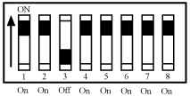
Configuration switches
There is a set of configuration switches on the underside of the drive,
shown below:

With the drive switched off, use the information below to select the
correct configuration for your system.
Note
For the drive to operate correctly, appropriate drivers and application software must be
loaded on the host computer.
Data Compression
Switches 1 and 2 are normally used to configure the way in which data compression is set
for the drive. The following table shows the available options:
| Switch 1 |
Switch 2 |
Meaning |
| On |
On |
Compression enabled at power-on with host control |
| On |
Off |
Compression enabled at power-on no host control |
| Off |
On |
Compression disabled at power-on. The host is allowed
to control compression |
| Off |
Off |
Compression disabled at power-on no host control |
When switch 1 is on, data written to the tape will be compressed without
the knowledge of the host.
Media Recognition System (MRS)
Switch 3 is used to configure the drive to respond to DDS Media Recognition System tapes:
| Switch 3 |
Meaning |
| On |
The Media Recognition System is disabled. All DDS
tapes are treated the same, whether they posses the Media Recognition stripes or not. |
| Off |
The Media Recognition System is active. This is the
default setting. Non Media Recognition System tapes are treated as if they are
write-protected. |
Switches 4 to 8
Switches 4 to 8 are used to specify connectivity and functionality according to host or
customer requirements. The default settings for all switches is on.
 

|

