LS Pro (Bonsai)
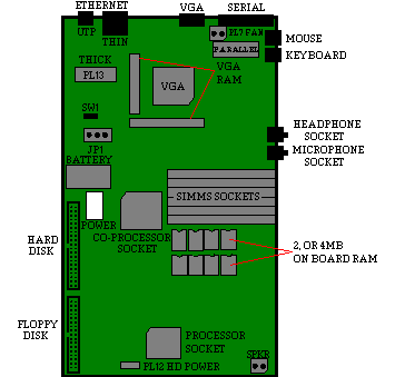
Motherboard Layout (Rev 1.1.20)

RAM Configuration
| 2MB on-board memory (386) |
On-board RAM |
SIMM bank 1 |
SIMM bank 2 |
SIMM bank 3 |
Total RAM |
2MB |
- |
- |
- |
2MB |
2MB |
2 x 1M |
- |
- |
4MB |
2MB |
2 x 1M |
2 x 1M |
- |
6MB |
2MB |
2 x 1M |
2 x 1M |
2 x 1M |
8MB |
2MB |
2 x 1M |
2 x 4M |
- |
12MB |
2MB |
- |
2 x 4M |
2 x 4M |
16MB * |
| |
| 4MB on-board memory (486) |
On-board RAM |
SIMM bank 1 |
SIMM bank 2 |
SIMM bank 3 |
Total RAM |
4MB |
No sockets |
- |
- |
4MB |
4MB |
No sockets |
2 x 1M |
- |
6MB |
4MB |
No sockets |
2 x 1M |
2 x 1M |
8MB |
4MB |
No sockets |
2 x 4M |
- |
12MB |
4MB |
No sockets |
2 x 4M |
2 x 4M |
16MB * |
* On-board memory
automatically disabled |
Ethernet Options
| On-Board Thick, Thin and UTP Ethernet. |
| For Token Ring use LS Rev 'F' Token Ring Module. |
Disk Drives
Switch Settings
| SW1 |
Switch Position Viewed from Front of Machine |
| Thick Ethernet |

|
| Thin Ethernet |

|
Additional Options
| Apricot LOC Technology security system |
| Single Chip VGA with 1MB of RAM and up to 1024 x 768 x 256
resolution. |
| Microsoft Windows 3.1 Business Audio Support. |
| PS/2 Mouse |
| 80387SX-33 Co-processor support (BN50157) |
Rear Panel
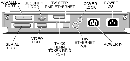
CMOS Discharge
To discharge CMOS use JP2
- Connect pins 1 & 2 (LEFT) to clear CMOS.
- Connect pins 2 & 3 (RIGHT) for normal use
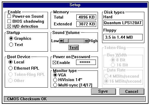
To enter the Setup Screen press ALT-S during POST.
Setup Screen

|