FT4200 Upgrading and Expansion (Rel 1.12.1)This explains
the procedure for upgrading the CPU to one of higher speed and also provides information
on upgrading the memory. You can also install expansion cards to increase your
system’s capabilities.
Your system can support up to four CPUs. They all must be of the
same speed and type.
Important Note
This system has been tested to comply with CE marking and its strict
legal requirements. Use only Apricot tested and approved parts. Failure to do so may
result in invalidating both the compliance and your warranty. All expansion cards must
carry CE approvals.
Gaining Access to the Machine Interior
To gain access to the interior of the machine, you must remove the side
panels. The following illustration shows the securing screws and key lock which are
present on each side panel:
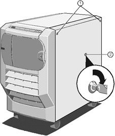 |
| 1 |
Floating Fasteners |
| 2 |
Keylock |
|
To remove the side panel:
1. Refer to the SMA and note down the value of the TimeOnCharge
variable. This value expresses, in seconds, the remaining charge in the UPS battery pack.
Since isolating the battery pack (see below) sets the TimeOnCharge variable to
zero, you will need to reset the variable in the SMA after you have completed the work and
set the switch back to the On position.
2. Power down the system to Standby mode.
3. Ensure that the battery pack is isolated (the circuit breaker switch
on the rear of the server must be in the Off position).
4. Disconnect the system from the AC supply.
5. Loosen the floating fasteners, located at the top left and right
corners of the panel, until they move in and out freely. These fasteners are mounted in a
spring fitting and should not be separated from the panel.
6. Insert the side panel key into the keylock and turn it ¼ turn
clockwise to unlock the panel. Your system is equipped with one pair of side panel keys.
Both keys in the pair will unlock both side panels.
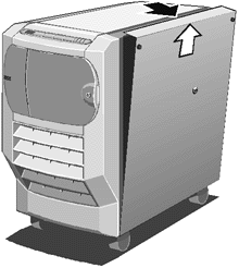
Press the panel firmly downwards, against the springs, in order to pull
it outward and then upward as shown:
 
Refitting the Side Panel
Use the following steps to refit the side panel:
1. Ensure that the lip on the inner surface of the side panel fits over
the chassis ridge at the panel bottom edge.
2. Press the panel downwards against the springs, then fit it in under
the top edge.
3. Tighten the floating fasteners.
4. Insert the side panel key into the lock and turn it clockwise as far
as it will go.
5. Push the lock inward until you feel the resistance of the metalwork.
6. Turn the lock ¼ turn anti-clockwise and remove the key.
7. Use the SMA and the front door key, as appropriate, to ensure that
Security is enabled.
 
Upgrading the CPU
Important Note
The procedures explained in this section are for authorised
engineers only.
The first two CPU positions are located on the motherboard, towards the
top of the electronics chamber. A second pair of processors can be located on an
additional card which may be fitted at the top of the motherboard.
To gain access, it is required to remove the protective metal plate
which covers the upper part of the electronics chamber. On completion of any work it is
important to replace this panel for airflow integrity.
Remove the securing screws as shown in the following diagram:
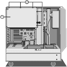 |
| 1 |
Protective Metal Plate |
| 2 |
Securing Screws |
|
2. Lift the metal plate away from the metalwork.
 
Memory and CPU locations
This diagram shows the positions of the CPUs and main memory:
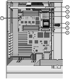 |
| 1 |
VRM for processor ‘B’ |
| 2 |
DIMM sockets 1-4 |
| 3 |
Processor ‘B’ |
| 4 |
Processor ‘A’ |
| 5 |
DIMM sockets 5-8 |
| 6 |
VRM for processor ‘A' |
| 7 |
Clock and multiplier SWs |
|
Caution
All electronic computer components are sensitive to static
electricity. Always take antistatic precautions before handling such components (see the
Appendix for more details). An earthing stud is provided at the rear of the server.
To remove the existing processor
1. If the system was in use just before starting this procedure, the
processor will be hot, wait at least 15 minutes for it to cool down.
2. If there is no processor fan, a strong spring clip secures the large
heatsink to the processor. Release the end of the spring from the hook on the front of the
ZIF socket with care and slide the heatsink clear. Handle carefully as there may be heat
transfer compound on the heatsink face.
There may be a power lead for a fan if the processor has one fitted in
the place of a simple heatsink. Take note of the fan power lead polarity before releasing
it from its board connection.
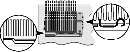
A lever attached to the ZIF socket secures the processor in the socket.
Unhook the lever from the locked position. Lift it upright (at right-angles to the
motherboard). There may be a little stiffness at the beginning and end of the lever’s
movement.
4. Lift the processor out of the socket and place it on an anti-static
surface outside the system unit. Hold the processor by its edges and avoid touching any of
the metal pins.
Warning
If the processor does not easily lift out of, or fit into the
socket, do not force it or damage may be caused to the processor and the socket. Consult
your supplier or an Apricot dealer.
To fit the upgrade processor
Complete kits of Processor, Spring clip, Heatsink and Voltage Regulator
Module (VRM8) are available from your Apricot dealer.
1. Ensure that the securing lever on the ZIF socket is still in the
upright position.
Caution
If the computer has more than one CPU fitted it requires all CPUs to
be upgraded. They must all be of the same speed and type.
Take the upgrade processor out of its anti-static packaging. Hold the
processor by its edges and avoid touching the metal pins. The processor and ZIF socket are
designed to ensure that the processor can only install in the correct orientation. (The
pin pattern is totally different at one end.) It will only fit into the socket one way.
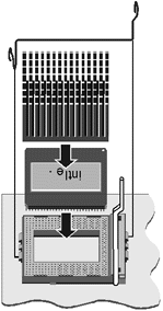
Place the processor in the socket, making sure that it is correctly
aligned and that you do not bend or otherwise damage the pins. Do not use
excessive force.
4. Move the ZIF socket lever to the locked position. Apply just enough
pressure to overcome the resistance offered by the lever. Ensure that it is firmly locked
into its down position.
5. Refit the heatsink if the new processor was supplied without one and
secure correctly the retaining spring. Ensure the heatsink is central on the
processor and is securely held.
If the spring is no longer required, remove it completely by disengaging
it from its hook on the rear of the ZIF socket.
The upgrade processor may have a fan power lead to be connected to the
pins on the board. The ‘Overdrive’ type processor however may have its own
internal connection for the fan power supply.
6. It is vital when fitting an additional processor, that the Voltage
Regulator Module (VRM8) is inserted into its socket/connector adjacent to the
processor’s ZIF socket. It will only fit one way.
Now adjust the processor multiplier and external bus clock speed
switches on the motherboard (in conjunction with the new processor’s data
sheet), as in the following tables. Note that all other switch positions are reserved.
External bus clock
| Frequency |
SW1-5 |
SW1-6 |
| 66Mhz |
off |
on |
| 60Mhz |
on |
off |
| 50Mhz |
on |
on |
|
Processor bus multiplier
| SW1-1 |
SW1-2 |
SW1-3 |
SW1-4 |
Factor |
| on |
on |
on |
on |
x2 |
| on |
off |
on |
on |
x2.5 |
| on |
on |
off |
on |
x3 |
| on |
off |
off |
on |
x3.5 |
| on |
on |
on |
off |
x4 |
|
Warning
Do not alter the processor or clock settings under normal operation
unless upgrading all the fitted processors. It could result in permanent damage to either
the motherboard or the processors.
Additional CPUs, ‘C’ and ‘D’
If there are two processors fitted to the motherboard and if it is
required to fit a third+fourth processor, the extra processor board will need to be
fitted.
The procedure for fitting processors to this extra board is identical to
that for the motherboard, but for safety and ease of assembly it is recommended to be
completed before installing the card in the system, on a suitable antistatic surface or
mat. The processors and VRMs must be exactly the same as the
ones fitted to the motherboard. The additional processor board must be inserted in the
slot at the top of the motherboard:
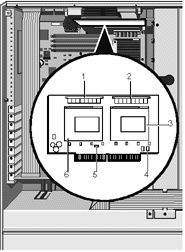 |
| 1 |
VRM for processor ‘D’ |
| 2 |
VRM for processor ‘C’ |
| 3 |
ZIF socket for processor ‘C’ |
| 4 |
Fan connection (if required) |
| 5 |
Fan connection (if required) |
| 6 |
ZIF socket for processor ‘D’ |
|
1. Disengage the termination board from its slot at the top of the
motherboard and place it in suitable packaging.
2. The additional CPU board then fits into the same socket, with the
processors facing downwards.
3. Fit the metal support strut into place. Hooks at one end fit into the
fan housing and the other end is fixed with a screw at the chamber rear. Ensure that it is
firmly fitted onto the edge of the CPU board.
Upgrading Memory
Important Note
The procedure explained in this section is for authorised engineers
only.
There are two memory locations each with sockets for four Dual Inline
Memory Modules (DIMMs). Slots are numbered from 1 to 8 (top to bottom).
Slots 1, 3, 5, 7, form bank one and
slots 2, 4, 6, 8, form bank two.
You must populate the slots according to the following rules:
If more than 1 DIMMs is to be fitted in a bank, they must all be the
same capacity. (See the supported memory configuration table overleaf).
EDO and FPM type DIMMs can be mixed.
Bank two can have different capacity modules, but must have the same
population of modules as bank one. It must also match the supported configurations in the
table overleaf.
Use only 3.3 volt, gold contact modules.
All fitted modules should be the same speed.
80ns, 70ns and 60ns are all supported, but 60ns may provide performance
benefits with some operating systems.
The BIOS will adjust to the speed of the slowest module if they differ.
The minimum configuration is one DIMM, but there are benefits in fitting
2 or 4 DIMMs, as 2 or 4 way interleave, respectively, then become available. The following
restrictions however, must be applied:
If memory is to be fitted in both banks their interleave population must
be identical, e.g. populating sockets 2 and 3 is not allowed. (see the scheme
tabled below.)
You must fill one, two or all four slots in bank one. Three DIMMs in a
bank is not supported. You must therefore fit 1, 2, 4, or 8 modules.
When 2 or 4 modules are to be fitted it is preferable to keep them in
one bank.
Interleave scheme
| Interleave |
BANK ONE |
BANK TWO |
| 1 way |
Socket 1 |
Socket 2 |
| 2 way |
Socket 1+3 |
Socket 2+4 |
| 4 way |
Socket 1+3+5+7 |
Socket 2+4+6+8 |
The following table lists the supported memory
configurations for bank one. Bank two when used must have an
identical number of modules. They may be of different value but must be a supported
configuration from this table.
| Total memory |
Socket 1 |
Socket 3 |
Socket 5 |
Socket 7 |
| 16-Mbyte |
8 Mb |
8 Mb |
- |
- |
| 16-Mbyte |
16 Mb |
- |
- |
- |
| 32-Mbyte |
8 Mb |
8 Mb |
8 Mb |
8 Mb |
| 32-Mbyte |
16 Mb |
16 Mb |
- |
- |
| 32-Mbyte |
32 Mb |
- |
- |
- |
| 64-Mbyte |
16 Mb |
16 Mb |
16 Mb |
16 Mb |
| 64-Mbyte |
32 Mb |
32 Mb |
- |
- |
| 64-Mbyte |
64 Mb |
- |
- |
- |
| 128-Mbyte |
32 Mb |
32 Mb |
32 Mb |
32 Mb |
| 128-Mbyte |
64 Mb |
64 Mb |
- |
- |
| 128-Mbyte |
128 Mb |
- |
- |
- |
| 256-Mbyte |
64 Mb |
64 Mb |
64 Mb |
64 Mb |
| 256-Mbyte |
128 Mb |
128 Mb |
- |
- |
| 256-Mbyte |
256 Mb |
- |
- |
- |
| 512-Mbyte |
128 Mb |
128 Mb |
128 Mb |
128 Mb |
| 512-Mbyte |
256 Mb |
256 Mb |
- |
- |
| 1-Gbyte |
256 Mb |
256 Mb |
256 Mb |
256 Mb |
Removing DIMMs
Caution
Before attempting to remove or fit a DIMM, be sure to take proper
antistatic precautions, such as using an antistatic strap. (See the Appendix for more
details on antistatic precautions). An earthing stud is provided at the rear of the
server.
If you wish to install an upgrade in a bank which is already occupied
you may need to first remove the existing DIMMs. For each DIMM in the bank:

Press gently the clips on each side of the socket gently outwards using
your forefingers. This will disengage the clips and lift the DIMM up and out of the
socket.
2. Taking care to avoid touching any of the components on the DIMM, grip
the top corners of the DIMM between thumb and first finger and carefully lift the module
out of the socket.
3. Place the DIMM in a suitable antistatic package.
Inserting DIMMs
Important
Apricot Computers Ltd extensively tests many types of memory
modules. DIMMs obtained from any other source cannot be guaranteed to operate correctly or
safely with the rest of the system and software. Non Apricot parts may invalidate both the
CE approvals and the system warranty.
For each socket in the bank:
The DIMM will only install in one orientation. There are indents along
the DIMM’s edge connector as shown:

Hold the DIMM with its metal connector strip nearest the board
surface.
Press the DIMM gently into the socket and ensure the end clip at each
end clicks into place, retaining the module in the socket.
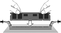
If the clips will not latch easily, remove the module and start again.
Do not use excessive force.
Installing and Removing Expansion Cards
Important Note
The procedures explained in this section are for authorised
engineers only.
The following illustration shows the positions of the expansion
card slots in the electronics chamber:
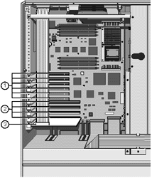 |
| 1 |
PCI Slots |
| 2 |
EISA/ISA Slots |
| 3 |
SMIC card (bottom slot) |
|
Important
You must always replace the System Management Interface Card in its
original fitted position, i.e. the bottom EISA slot.
Installing
1. Study the expansion board’s installation guide and follow its
directions. The guide should tell you what kind of slot (i.e. PCI or EISA/ISA) you will
use and whether there are any jumpers or switches on the card that you need to configure
before fitting.
2. Remove the blanking plate from the rear panel access opening that
corresponds to the chosen PCI or EISA slot.
Remember that one EISA/PCI slot is shared and therefore can only accept
one card of either type.
3. Detach the SMIC ribbon cable from the SMIC card temporarily, to allow
cards into the chamber.
4. Now fit the expansion card carefully into the slot. You can only
install it in one orientation. If your card is full-length, be sure to insert one edge
into the slider guide, attached to the cooling fan assembly metalwork, as you fit the
card.
Position rules
Additional SCSI controllers
These must be fitted in one of the bottom three PCI slots to avoid
boot-up conflicts with the onboard controllers.
RAID controllers
These should also be fitted to the lower slots
PCI Ethernet cards
Fit from the topmost PCI slot downwards
EISA Ethernet cards
Any slot bar the lowest, which is strictly reserved for the SMIC
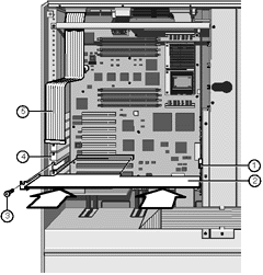 |
| 1 |
Card end guide/support |
| 2 |
Expansion Card |
| 3 |
Securing Screw |
| 4 |
Blanking plates |
| 5 |
SMIC cable |
|
1. Ensure that the card is firmly seated in its slot, but
do not use excessive force.
2. Fasten the card in place using the blanking plate securing screw.
3. Fit any required cables to the board, ensuring their correct
orientation. Do not allow them to obstruct airflow from any of the cooling fans.
4. Refit the SMIC ribbon cable to the SMIC card.
5. Run the EISA Configuration Utility (ECU) to complete the installation
process. Full details are in the preceding chapter.
Caution
Remember to copy the RAMdrive back to the Flash disk on the ECU.
Otherwise any configuration files added or updated will be lost when you exit the ECU.
Removing
1. Unplug all cables connected to the board and remove them completely.
2. Remove the securing screw and pull the board out of the slot, leaving
an empty space on the rear panel for the blanking plate again.
3. Replace the original blanking plate to cover the rear opening to
maintain airflow integrity.
4. Run the EISA Configuration Utility (ECU) to inform the system that
you have removed the board.
Caution
Remember to copy the RAMdrive back to the Flash disk on the ECU.
Otherwise all the updated configuration files will still be present when you exit the ECU.
 

|

