FT4200 Setting Up and Operating (Rel 1.12.1)Front View
The following illustration shows a front view of the server with the
front drive bay door open:
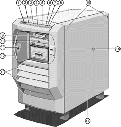 |
| 1 |
Diagnostic Codes LCD |
9 |
3.5" Floppy Drive |
| 2 |
Power On Button |
10 |
5.25" CD ROM Drive |
| 3 |
Control Button |
11 |
Drive Bay Door Keylock |
| 4 |
Standby Button |
12 |
Drive Bay Door |
| 5 |
Reset Button |
13 |
Air Intake Vents |
| 6 |
Infrared Sensor |
14 |
Removable Side Panel |
| 7 |
UPS LED |
15 |
Side Panel Keylock |
| 8 |
Power LED |
16 |
Side Panel Floating Fasteners |
|
Rear Panel
The rear panel contains the various ports and connectors as shown in the
following illustration:
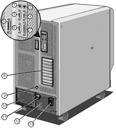 |
| 1 |
Keyboard Connector (PS/2) |
8 |
Expansion Slot Openings |
| 2 |
Mouse Connector(PS/2) |
9 |
Stud for Antistatic Strap |
| 3 |
Serial Port COM2 |
10 |
Removable UPS Battery Pack |
| 4 |
Serial Port COM1 |
11 |
UPS External Circuit Breaker |
| 5 |
SMC Modem Port |
12 |
Uninterruptible Power Supply |
| 6 |
Video Connector |
13 |
AC Power Socket |
| 7 |
Parallel Port |
|
|
|
Hard Disk Subsystem
The hard disk subsystem is the area in which the hard disks are located.
It occupies the lower portion of the disk drive chamber. It can be configured to
accommodate up to 20 hard disk drives.
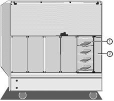 |
| 1 |
Disk Subsystem |
2 |
Cooling Fan Assembly |
|
Removable Media Drive Bay
The removable media drive bay is the area which can contain drives such
as floppy, CD ROM and tape backup drives. The bay will accommodate up to four half-height
5.25-inch drives. Your system will contain at least one 3.5-inch 1.44-Mbyte floppy disk
drive.
User access to the drive bay is through the lockable drive bay door on
the front bezel. The lock on the door is fitted with a sensor which, when security is
enabled, sounds an alarm if the door is opened without using the key to unlock it, i.e. if
it is forced.
Motherboard
The motherboard contains the various disk controllers and other
electronics necessary to control the server’s functions. It contains the memory and
first two processors as well as PCI and EISA expansion slots.
Uninterruptible Power Supply
This power supply is designed to keep your system powered up for a
limited period of time after, or during a power failure. It is equipped with an on-line
removable battery pack and will give you enough time to shutdown the network and the
server without losing valuable data. The power supply, including the battery pack,
occupies the entire lower level of the server chassis.
The UPS will maintain power to the system for a minimum of 4 minutes in
a fully-laden system, i.e. equipped with 20 hard disk drives. This time will be longer in
a system equipped with fewer drives.
Cooling Fans
Your computer is equipped with six thermally controlled and alarmed
cooling fans, three on each side of the machine. These will prevent overheating by
maintaining an appropriate temperature inside the system.
In addition there are two cooling fans within the UPS unit.
Caution
You must maintain at least 15 cm space around the computer for
adequate ventilation. Otherwise damage could result from overheating.
Setting Up Your System for the First Time
After you have unpacked the server and rolled it into position, use the
jacking mechanism on the front castors to immobilise it. Then go through the following
steps to start up the system:
Connect the monitor signal, keyboard and AC power cables to the sockets
on the server’s back panel.
See the guide supplied with the monitor for details on its connections
to an AC supply and general information about its signal cable.
Establish the appropriate link which will enable you to run the System
Management Application (SMA), such as:
Direct link to another PC. In this case, use the supplied serial-to-PC
cable to connect the SMC modem port to the serial port on the separate diagnostic
computer.
Modem link to a computer at another location. Use the supplied
serial-to-modem cable to connect the SMC port to the modem.
In some cases you can also run the SMA over the network itself, from one
of the connected computers, depending on the operating system.
Switch the AC supply on, followed by the UPS isolation switch on the
rear of the system. (For safety during transportation, this is locked in the off position
with a strap).
The Uninterruptible Power Supply LED should display steady green
(battery fully charged) or flash green (battery pack is charging). If the LED is flashing,
it will take a maximum of 36 hours to charge the batteries from full discharge.
The system is now in Standby mode.
Locate and press the Power On button to switch the machine on.
When the system is up and running normally following boot-up and all
software loaded, the display code on the front LCD panel will be 0000. If any codes
appear other than normal procedure codes, then refer to the chapter dealing with
Diagnostic codes towards the end of this handbook. Some codes are transitory, being way
markers for the boot-up process.
Before proceeding further, read carefully the following pages in this
chapter. They contain important information about the controls and their functions.
Using the Front Panel
This section describes the functions of the front panel during normal
operation.
Caution
Do not place any large or heavy objects on the top, especially near
to the front facia. Likewise avoid leaning on the machine. It may inadvertently cause the
operation of one or more front panel buttons.
 |
| 1 |
Diagnostic LCD |
5 |
Reset Button |
| 2 |
Power On Button |
6 |
Infrared Sensor |
| 3 |
Control Button |
7 |
UPS LED |
| 4 |
Standby Button |
8 |
Power LED |
|
Power On
Press this button to switch the system on from Standby mode. The Power
LED will light up and the system will initiate its boot sequence. Diagnostic codes,
expressed as hexadecimal numbers, will appear as a matter of course on the LCD screen on
the Front Panel (see the chapter Diagnostic Codes Reference for details). The
screen will display the SCSI ID number for each of the SCSI devices installed in your
system. What happens after this depends on how your Apricot has been configured, i.e.
which operating system or other software may be installed. Check with your supplier if you
need more details.
Control
Press this button to silence alarms and clear LCD display codes that are
produced because of internal errors and power failures (but not security alarms).
Pressing Control at the end of firmware initialisation forces the System
Management Controller (SMC) to execute the code of the EPROM instead of the Flash ROM,
even if the version in the Flash is newer than that of the EPROM. This allows you to boot
from EPROM if there is something wrong with the Flash code.
Note
It is good practice to warn anyone who may be accessing the system
remotely, i.e. using the SMA from a remote computer via the modem port, before you press
the Standby button.
Standby
After you have instructed all network users to close their applications
down and log off the network, hold this button down for a specific period of time before
the system initiates a shutdown sequence to Standby mode. The system will display the code
1200 on the LCD and sound a tone. Continue to hold down the Standby button until
the tone stops, at which time the shutdown sequence begins. In Standby mode, the mains
electricity supply keeps the battery pack fully charged, but there is no DC power supplied
to the system. Use the System Management Application (SMA) to specify, in seconds, how
long you must hold down the button before the shutdown sequence begins (see the SMA
User’s Guide). The default is 3 seconds.
Press Standby and Control simultaneously to cancel the current Standby
sequence. (Only if last client is loaded)
Note
When accepted, the Standby timer requests that the operating system
be shutdown, thus the final screen message will be "Shutdown or Restart OS." If
Restart is selected the motherboard is reset and the POST sequence initiated. During this
period the SMC timer is still running and can move the system into Standby at any point. To
prevent possible data loss or corruption it is recommended to always select Shutdown in
this situation.
Reset
Press this button to initiate a hardware reset, but only if it is
absolutely necessary. The LCD will display 1400. You must hold the button down
until the accompanying tone stops sounding. Use the System Management Application (SMA) to
specify how long, in seconds, the reset tone will sound (see the SMA User’s Guide).
The default is 3 seconds.
Press Reset and Control simultaneously to cancel the current reset
sequence. (Only if last client is loaded)
Special Button Functions
Caution
Do not use these functions unless there is serious problem with the
system and it is absolutely necessary.
Pressing Standby, Control and Reset simultaneously while the front drive
bay door is unlocked switches the system into a mode in which these three buttons
have special functions. The LCD displays 8888 to indicate this mode. The following
paragraphs describe the special function of each button.
Standby or Reset - Pressing either of these buttons initiates a
memory dump to the central processing unit by activating and then deactivating the
Non-Maskable Interrupt (NMI) signal via the diagnostic processor. The effect of this
action will depend on the operating system. You can then use the appropriate function of
the network operating system to examine the contents of the dump.
Control - Pressing this button initialises the modem, which is connected
to the SMC modem port on the back panel of the server. If the modem initialisation is
successful, the LCD displays the code 0000. If the initialisation is unsuccessful, the LCD
displays 0F4D or 0F4E.
Standby + Reset - Pressing these buttons simultaneously clears the LCD
and then releasing them executes an independent SMC reset. This would only be necessary if
a major problem or error had occurred in the system, which is unlikely.
All 3 - Displays SMC BIOS version on the LCD.
If you do not press any buttons for ten seconds, the system returns to
normal mode.
UPS and Power LEDs
The UPS and Power LEDs indicate the state of the system as follows:
UPS LED
When this LED shows steady green, it means that the system is powered by
mains electricity and the batteries are fully charged.
Flashing green means that system is powered by mains electricity and the
batteries are in the process of charging. This will usually be the case after the system
has been without mains electricity, i.e. disconnecting the plug or a power failure.
Steady amber indicates that the system is drawing its power off the
batteries, i.e. there is no mains electricity. As soon as mains electricity fails, an
alarm sounds.
Flashing amber indicates that the battery pack is about to fail.
Off shows that the batteries are disconnected because the circuit
breaker switch on the back of the machine is in the Off position or the system is
disconnected from the mains.
Power LED
Steady green means that the system is on and powered.
Security
Your Apricot is equipped with a security system to help prevent
unauthorised persons tampering with the front panel buttons and gaining access to the
interior of the system.
Security is enabled within the System Management Application (see the SMA
User’s Guide, the Event Manager User’s Guide or the on-line help
within the SMA software). Once security is enabled, the key to the removable drive bay
door at the front of the machine serves as the security token:
If the door is closed and has been locked with the key, the screen is
blanked, the keyboard is disabled, the security alarm is activated and will sound if there
is a violation.
Unlocking the door unblanks the screen, enables the keyboard and
deactivates the security alarm.
Note
When security is enabled and the door locked, you can use the KeyLOC
infrared card to unblank the screen and enable the keyboard temporarily. The card will
also silence a security alarm. Use the card again to blank the screen and disable the
keyboard.
The following actions are security violations and will set off the alarm
when the drive bay door is closed and locked and security is enabled:
Forcible opening (i.e. without the key) of the removable drive bay door.
Removal, with or without the key, of one or both of the side panels.
Pressing the , or buttons individually or in any combination.
To silence the alarm, use the key to unlock the drive bay door. If the
door is already unlocked when the alarm sounds, first lock and then unlock the door.
Alternatively, use the KeyLOC card to silence the alarm.
Automatic Failure Recovery
As with any computer system, your server may develop a hardware or
software fault, which, for example, may only manifest itself intermittently, that causes
the system to hang. If this happens, the server is capable of resetting itself
automatically. This is particularly useful if the server is unattended some or all of the
time.
Whether the server is able to rebuild the complete network environment,
together with application programs, after an automatic reset depends on the operating
system. The SMA contains several variables which govern the behaviour of automatic failure
recovery:
Machine Status
Watchdog Timeout
Watchdog Timer Reboot Count
Watchdog Timer Timeout Action
You can make settings for these variables to enable, disable or modify
their effects. The on-line Help system within the SMA contains details of all of these
variables and how to make the appropriate settings.
The Flash Memory
The Flash is a special portion of read-only memory (ROM). It differs
from conventional ROM in that its contents can be updated, but it still preserves its
information when system power is off. The following components of your server contain
their own portions of Flash memory:
The motherboard - This Flash stores the BIOS information for the
motherboard.
The System Management Controller - This Flash stores the BIOS and
firmware which control the SMC and the Front Panel.
The System Management Interface Card (SMIC) - This is the main Flash,
also referred to as a Flash Disk. It contains bootable DOS, its own BIOS and a Flash Disk
Utility program which affects the other portions of Flash memory. The Flash Disk Utility
also runs the EISA Configuration Utility (ECU).
Your access to the Flash is via a RAMdrive. This enables you to treat
the Flash almost as if it were a disk drive. The RAMdrive and the Flash Disk each have a
capacity of 2 Mbytes. Because the Flash Disk contains the operating system files, the
server can boot from it if the normal system hard disk boot process fails. You can also
copy files to the Flash Disk, e.g. hardware component configuration (.CFG) files which the
ECU uses. If you are using the RAMdrive to enter details of an add-in card, you must
remember to update the Flash disk before closing.
The Flash Disk Utility
The RAMdrive is necessary is because the Flash Disk is write-protected
and therefore you cannot copy anything directly to it. The purpose of the Flash Disk
Utility is to enable updates to the information held in any portion of Flash memory, such
as new BIOS versions or hardware information stored in the ECU.
To run the Flash Disk Utility locally, press F2 during the hardware boot
sequence but before the operating system loads. This instructs the server to boot from the
Flash Disk and load the utility. The screen then displays a menu with the following
options:
Receive File - This option copies a file from the server to the
workstation which is running the SMA. If you are not using the SMA and are running the
utility locally, the file is copied from the Flash to a floppy disk. After you select 1
from the menu, select the file you want to copy and press the ENTER key.
Transfer File - This option is the opposite of Receive File, i.e.
it copies a file from the SMA workstation to the server or, if you are running the utility
locally, from a floppy disk to the Flash.
Run Configuration Utility - Select this option to run the ECU
(see "Using the EISA Configuration Utility", earlier in this chapter).
Upgrade Motherboard BIOS - This option enables you to upgrade the
motherboard’s BIOS with a new version of BIOS information. This information is in the
form of a binary file. When you select this option, you have the choice of either copying
the binary file to the RAMdrive and updating the BIOS in one operation or, if the correct
binary file is already copied, just performing the update.
Upgrade SMIC BIOS and Upgrade SMC Firmware, are similar to
option 4.
Upgrade Flash Disk - This option copies the contents of the
RAMdrive to the Flash Disk, thereby making the Flash identical to the RAMdrive.
Caution
You must perform this step to copy information on add-in expansion
cards back to the Flash Disk, after installing any card and making the necessary entries
in the ECU on RAMdrive, All details will be lost to the system on a re-boot or reset.
Reset Flash Disk for Upgrade - This option does the opposite to
option 8, i.e. copies the contents of the Flash to the RAMdrive, thereby making the
RAMdrive identical to the Flash.
Edit a File - Use this option to load a file into the Microsoft
Edit program for editing.
Exit - This option exits from the Flash Disk Utility and passes
control back to the SMA.


|
