Having followed the preliminary tasks as detailed:
1. Unplug all cables and leads from the back panel connectors (i.e.
serial, parallel, video, keyboard, mouse) on the motherboard ports and from any expansion
cards.
2. Remove the screws which secure the metal plate over the electronics
chamber. The screws are along the top and right edges of the plate as shown in the Owner's
Handbook.
3. Rotate the right edge of the plate slightly towards you and unhook
the left edge. Removing the plate uncovers the motherboard.
4. Remove the six screws from the periphery of the sub-plate which
surrounds the serial, parallel and video connectors on the rear panel of the server.
5. Disconnect the ribbon cable from and remove the System Management
Interface Card (SMIC) and put the card in a safe place.
Caution
All boards and assemblies should be placed on an antistatic surface
or within an antistatic container as they are removed from the server.
1. Remove all card supports across the motherboard section.
2. Remove the memory boards, CPU boards, plus any other expansion cards.
3. Disconnect all ribbon and power cables from the top of the board.
Remove completely all the short ribbon or power cables between the
motherboard and the power distribution board.
Caution
It is vital that you remember the exact cable and connector
arrangement of the hard disks, particularly when using a RAID configuration, especially if
there is an additional SCSI control board fitted in the system. If you fail to restore the
arrangement so that all cables and plugs are as they were originally, all the data on the
hard disks could be lost
4. Unplug the two SCSI interface cables from the connectors at the
bottom of the motherboard.
One of these SCSI cables goes via the HDD module 'B' to the 5.25"
removable media drive bay. This cable should be released from its restraints, disconnected
at all points between the motherboard and the drive end and all sections removed from the
casing.
Check the jumper setting on the module topboard. The link must be set to
terminate the SCSI bus.
5. Now remove the 14 screws which secure the motherboard to the centre
spine of the server, as shown in the Shogun Owner's Handbook.
6. Lift the motherboard clear of the casing.
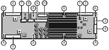
The motherboard power distribution panel is fixed to the inner roof of
the electronics chamber and is positioned at right angles to the motherboard. The
illustration below shows the connectors and the eight securing screws on the board. This
should not normally need to be removed.
1. Disconnect the busbars from the board, then disconnect them from the
power supply at the bottom of the chamber. They are no longer needed.
2. Disconnect the SMIC ribbon and remove it from the casing. It is to be
replaced by a longer one.
3. Ensure that the power and ribbon cables to the motherboard have been
removed. The replacement cables are different.
Check that the board is revision /D or later, particularly if the
additional CPU card is to be fitted, The Pentium Pro takes far more power. The Rev
/B is easily identified by its having a small power module the size of a matchbox in the
centre, while the Rev /D has a very large heatsink covering a large area of the board, as
can be seen from the illustration below.
If there is a Rev /B power board then it must be upgraded to Rev
/D or later. If the customer has already had a second Twin Peaks board fitted, the power
board should already be rev /D, or higher.
Other modifications may need to be made to early versions of this power
board if the additional CPU board is to be fitted. If in any doubt, check with Apricot
Technical Support Department.

| A |
Mounting screw holes (x8) |
| 1 |
Loudspeaker connection |
| 2 |
Data from motherboard |
| 3 |
Cooling fan connector |
| 4 |
Aux. power connector |
| 5 |
SMC ribbon connector |
| 6 |
SMIC ribbon connector |
| 7 |
Power to/from motherboard |
| 8 |
Power to/from motherboard |
| 9 |
Power to/from motherboard |
| 10 |
3.3V supply to motherboard |


