FT4200 Redundant Power
Supply (N+1)
Rear Panel
Power Supply and optional Battery Back Up unit
(BBU)
Module Power Output
Removing and fitting power modules
Removing the complete Power Tray
Optional Battery backup unit (BBU)
Battery Isolation (Fireman’s Switch)
System management controller (SMC)
Rear Panel
The rear panel contains the various ports and connectors as shown in the
following illustration:
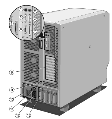 |
1 |
Keyboard Connector (PS/2) |
2 |
Mouse Connector (PS/2) |
3 |
Serial Port COM2 |
4 |
Serial Port COM1 |
5 |
SMC Modem Port |
6 |
Video Connector |
7 |
Parallel Port |
8 |
Expansion Slot Openings |
9 |
Stud for Antistatic Strap |
10 |
Optional Battery back up unit |
11 |
Battery isolation link |
12 |
AC Power Socket |
13 |
Power Supply modules |
|
 
Power Supply and optional Battery Back Up unit (BBU)
The power supply itself can consist of the minimum of one plug-in module
or the maximum of four. Each module can provide up to 267W to the computer’s power
requirements (see chapter 10 of the Owner's Handbook for further information). If there is
more than one Power Module, the computer may be able to continue to operate if one module
should fail, depending upon the configuration. When considering any additions to the
computer hardware, the power requirements should be assessed prior to their installation.
When the BBU is fitted, the complete power supply becomes an uninterruptible power supply
(UPS) and is designed to keep your system powered up for a limited period of time after,
or during, a power failure. The optional on-line removable BBU will provide time to
shutdown the network and the server without losing valuable data.
The UPS should maintain power to the system for approximately 4 minutes in a fully-laden
system, i.e. equipped with 20 hard disk drives. This time will be much longer in a system
equipped with fewer drives.
Note
In the event that the mains power fails, the LCD will display a countdown of the number of
seconds remaining until the (optional) battery back up unit is fully discharged. The Event
Manager User’s Guide contains more details about this feature.
 
Module Power Output
The power section is, in total, rated at: (output of 3 modules at 267W
per module)
+5V rail at 81A
+12V rail at 33A
-5V rail at 500mA
-12V rail at 500mA
5V standby rail at 800mA
The above ratings are for three power modules, the fourth being a
‘redundant’ module.
The first two are for the busbars for the motherboard and the hard drive
power board, the rest are taken via the multiway cables to their various destinations.
Adding hard drives, extra processors or multiple expansion cards may require the addition
of further power modules, contact your Apricot supplier for details.
 
Removing and fitting power modules
The power tray will be fitted with at least one power module, or up to a
maximum of four.
Depending on the system configuration and the number of working modules
fitted, one power module may be removed without shutting down the whole system, providing
the remaining power modules can cope with the system load. See above for power module
rating information.
It is advisable, if unsure, to fit a spare unit first if the computer
cannot be shut down. The modules can be hot-swapped.
Any failed unit will display a red LED on its rear plate, or be
completely unlit, while healthy units display a green LED. The modules are easily removed
and fitted.
To remove a module
Loosen the floating fasteners, located at the top and bottom of the
module to be removed, until they move in and out freely.
These fasteners are mounted in a spring fitting and should not be
separated from the module.
Gently but firmly pull on the handle until the module slides out. There
will be some resistance from the rear socket.
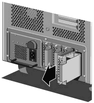
Power Module removal and refitting
To fit a module
Carefully slide the module into the internal guide rails and press
firmly into the rear socket.
Fix into position with the retaining fasteners. Do not overtighten.
If the module is being fitted to a live system, the red LED will
initially show during the unit’s self test. Then the green LED will come on to
indicate the module is working correctly. If the computer has been powered down, all
modules will briefly show red LEDs on power-up.
 
Removing the complete Power Tray
Warning
There are very few circumstances that would require the removal of the Power Tray,
but details are given here for completeness. It is recommended that work on the tray
should only be undertaken by a service engineer, with someone to assist, as the tray is
very heavy.
It is vitally important to ensure that the system is correctly
shut down. If a BBU is fitted, the battery link must be removed and the system
disconnected from the mains electricity supply.
Remove the motherboard cooling fan assembly as detailed in chapter 8 of
Owner's Handbook.
First detach two pairs of motherboard busbars and then the set of 3
busbars under the cooling fan assembly as shown in the following diagram.
If necessary, remove some of the expansion cards to improve access to
the busbars. You may also need to unplug some of the data cables which are connected to
the hard disk drive modules.
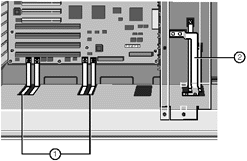 |
1 |
Motherboard Busbars |
2 |
Busbars for Hard Disk Power Distribution Panel |
|
Busbars
Caution
It is vital that you remember the exact cable and connector arrangement of your
hard disks, particularly if you are using a RAID (Redundant Array of Independent Disks)
configuration. If you fail to restore the arrangement so that all cables, plugs and hard
disks are as they were originally, you risk losing all the data on your hard disks.
Make sure that there is enough clearance between the busbars and their
power supply connections to allow the unit to slide freely, you may need to remove the
busbars completely.
Unplug three cables from the power supply as shown over.
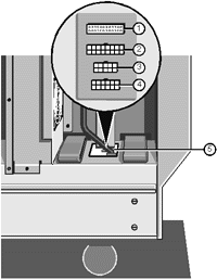 |
1 |
System Controller Connector (Ribbon) |
2 |
Motherboard Auxiliary Power (16-way) |
3. |
Not used |
4 |
Removable Media Bay Connector (12-way) |
5 |
Cable Connector Group |
|
Disconnecting Power Supply Cables
Loosen four floating fasteners, two on each side of the server, until
they are free of the power supply unit, as indicated in the next illustration.
Warning
This Power supply is heavy. It is strongly advised to have a second person to
assist before either fully removing the assembly from the server, or picking it up to fit
it back into the server.
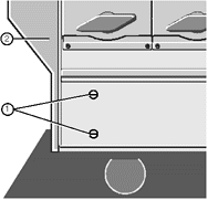 |
1 |
Floating Fasteners |
2 |
Front Bezel |
|
Power Supply Floating Fasteners
Now remove six screws on the back panel of the server, as shown:
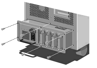
Power tray Securing Screws
Using one or two of the handles, pull the unit carefully forward
about 8 to 10cm, until a set of concealed busbar bolts become visible through one of the
motherboard chamber busbar windows. Remove these bolts.
Continue pulling, this time using the main PSU flange, until it is a
little less than halfway out (about 30 cm), just before it begins to tip towards you.
The second person should assist, on the opposite side of the unit, from
this point onwards.
Place your hands under the metal casing of the unit as indicated by the
arrows in the following illustration:
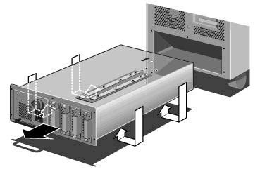
Power tray Removal
Slide the unit out slowly until it is free from its housing. Now
rest the unit on the floor or a suitable workbench. Do not drop it.
Fitting
With the help of the second person on the opposite side, place your
hands underneath the power supply as indicated by the arrows in the illustration above.
Now carefully slide the unit almost all the way into the chassis.
Use the front motherboard chamber busbar window to fix the bolts that
hold the power distribution board to the output connections of the power tray. Then slide
the tray fully in.
Caution
The hardware used to hold the busbar connections must be tightened using a torque
wrench set to 5 Newton meters (Nm).
Secure the unit to the chassis with the six screws as shown in Figure
10-6.
Now tighten the four floating fasteners, two on each side, located
towards the front of the machine.
Plug the cables into their connectors on the power supply.
Note that these connectors are keyed and can only be
fitted in one position.
Attach the set of 3 busbars to the HDD power board. Then attach the two
pairs of busbars to the motherboard.
As with the cables, it should not be possible to fit these bars
incorrectly.
Fit the motherboard cooling fan assembly.
Refit any expansion cards you may have removed to improve access.
Caution
It is vital that you remember the exact cable and connector arrangement of your
hard disks, particularly if you are using a RAID (Redundant Array of Independent Disks)
configuration. If you fail to restore the arrangement so that all cables, plugs and hard
disks are as they were originally, you risk losing all the data on your hard disks.
 
Optional Battery backup unit (BBU)
Warning
The power supply tray can be equipped with an optional BBU. Although it is a
replaceable unit, (information on removal and refitting is given below) it MUST ONLY BE
FITTED, or removed, by a suitably qualified service engineer.
Initial installation of the unit MUST only be carried
out by a service engineer visit to correctly setup the system to accommodate a BBU.
Contact your Apricot supplier for details.
Initial installation
Only be undertaken by a service engineer.
Shut down the system and disconnect from the supply.
Remove the blanking plate but retain the fixing screws.
Reach inside the BBU space and detach the small printed circuit board
from the clip-in mounting (this may be easier with a long screwdriver, due to limited
space).
Disconnect the wiring harness from the rear BBU edge connector and
remove the assembly from the chassis completely.
Fit the BBU into the power tray as detailed on the following page.
Important - Warning
The battery pack contains lead acid batteries. In the EEC the
directive 91/157/EEC (plus subsequent amendment 93/86/EEC) designates batteries containing
lead to be handled as a dangerous substance.
Similar regulations will apply in other countries.
The battery pack must only be removed by a qualified electrician and
must not be disposed of in domestic waste.
Removing
Ensure the system is shut down as detailed in chapter 3.
Ensure that you remove the BBU isolation link.
Remove the fastening screws as shown in the following diagram:
INSERT DIAG HERE
Battery Backup Unit
Pull the BBU handle carefully. There will be initial resistance due to
the power connector at the rear. Slide the unit out slowly . It is heavy.
Now with a slight lift, you can remove the BBU clear. Place it only on a
clear flat surface.
Warning
The BBU even when withdrawn may still contain a high charge.
Handle with extreme care.
Fitting
Carefully lift the BBU into position and slide it slowly into the
chassis.
Push the unit the rest of the way into the chassis.
Press firmly into the socket.
Refit the retaining screws as shown in the above Figure 10-8.
Fit the BBU isolation link.
 
Battery Isolation (Fireman’s Switch)
The BBU link can be used to connect to the Building Fire Services power
isolation and safety mechanisms if required. This is a common for big buildings or
businesses having telephone exchanges and air conditioning etc., but often overlooked
within large computer installations and networks.
The BBU isolation link is essentially a mini-plug, complete with cable
grip, having the two small pins internally connected. This connection can be broken and
the terminals wired to external cabling.
Screened cable should be used to connect to the isolation switch or
power panel relay, which should have a normally closed (healthy) contact. For further
information contact either your supplier, or Apricot Computers Limited, Technical Support
department.
 
System management controller (SMC)
Removing
Take careful note of where each connection is from and unplug three
ribbon cable connectors, the power connector, three fan connectors, two thermistor
connectors and one keylock sensor cable connector as shown in the following diagram.
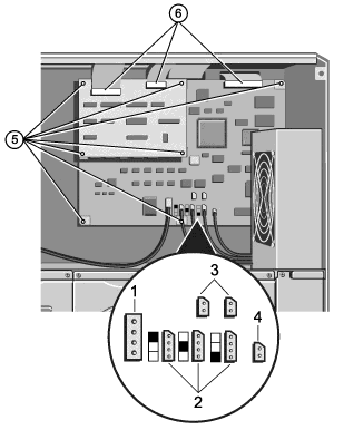 
|
1 |
Power Connector |
2 |
Fan Connectors |
3 |
Thermistor Connectors |
4 |
Keylock Sensor Connector |
5 |
Securing Screws |
6 |
Ribbon Cable Connectors |
|
System Management Controller Board
Remove the securing screws detailed above.
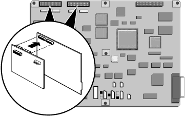
Carefully unplug the SMI2C daughterboard and put in a safe place.
Remove the four stand-off screwlock pillars from the SMC board that are
used to mount the SMI2C daughterboard.
Remove the two screw lock posts on the 25-way SMC serial port connector
which is visible on the server’s back panel and lift the SMC board clear.
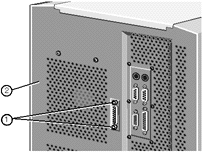 |
1 |
Screw Lock Posts |
2 |
Back panel |
|
SMC Serial Port Screw Lock Posts
Fitting
Feed the 25-way serial port connector through the opening in the back
panel.
Fasten the board to the centre spine using the four screwlock stand-off
pillars as previously removed.
Fasten the two screwlock posts into place at both ends of the 25-way
connector on the back panel. Do not overtighten.
Plug in the SMI2C daughterboard to the top left sockets of the SMC.
Refit the remaining screws as shown in Figure 6-1.
Plug the ribbon cables, power cable, fan and associated thermistor
cables and the keylock sensor cable into their respective connectors on the SMC board as
shown in Figure 6-1.
Ensure the daughterboard is correctly seated on the connectors at the
top left of the SMC board and that the correct two ribbon cables are fitted to the sockets
on it.
Caution
Ensure the ribbon cables from the front panel and the PSU are in their correct
positions or damage will be caused to the SMC board.
Against each fan connector on the board there is a graphic which
indicates which fan cable should be plugged in:
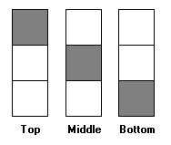
The middle and bottom fans in this series are located below
the SMC board in the disk subsystem area.
 

|


