 |


|
|
FT1200 'Crinkle' DK440LX Motherboard -
Processor Upgrade
To Remove a Processor
To Install a Single Processor
To Remove the Termination Card
To Install the Termination Card
To Install a Second Processor
To Set the Processor Speed
Processor Upgrades - Introduction
If your motherboard has one processor, you can upgrade the computer by
replacing this processor with a faster one, or by installing an application processor.
If your motherboard has two processors, you can upgrade by replacing
these processors with two faster processors.
If you install two processors, make sure they have:
- Identical speeds and voltages.
- The same stepping or a difference of no more than one stepping. Processor
stepping is designated by a five-letter code, for example, SL28R, printed on the top edge
of the S.E.C. cartridge.
Note:
If there is only one processor on a motherboard, it must be fitted in
the boot processor Slot 1 connector. In a single-processor configuration, you must install
a termination card in the empty application processor Slot 1 connector to ensure
proper operation of the computer.
Warning:
In all instances you must remove the rear drive carrier and the main
cross strut of the chassis to safely access the system processors.
The rear drive carrier assembly has a large cooling fan fitted to the
rear. It is essential that care is taken with this. It must be correctly refitted and
reconnected after you have finished your work.
 
To Remove a Processor
If you are upgrading a single processor, you need to remove the existing
processor
- Take suitable anti-static precautions.
- Turn off the computer, disconnect the computer’s power cord, and
disconnect all external peripherals.
- Remove any peripherals that block access to the processor.
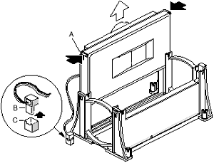
- Processors supplied to you by Mitsubishi will have a standard heatsink.
However, if your existing processor has a fitted fan, remove the fan heat sink power cable
connector (B) from the motherboard fan connector (C).
- To remove the processor from the Slot 1 connector, press in on the
latches (A) and pull the processor straight up as shown above.
- Store the processor in an antistatic package.
 
To Install a Single Processor
To install the processor:
- Take suitable anti-static precautions.
- Turn off the computer, disconnect the computer’s power cord, and
disconnect all external peripherals.
- Remove any peripherals that block access to the boot processor
Slot 1 connector.
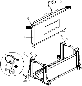
- If a processor is installed in the boot processor Slot 1, remove it.
See "How to Remove a Processor" as previously detailed.
- Remove the new processor from its antistatic package.
- Orient the processor (B) so that the heat sink faces the back of the
motherboard. Slide the processor into the retention mechanism (C). Ensure that the
alignment notch in the S.E.C. cartridge fits over the key in the Slot 1 connector.
- Press down firmly on the processor until it is seated in the boot
processor Slot 1 connector and the latches (A) on the processor lock into place.
- Processors supplied to you by Mitsubishi will have a standard heatsink.
However if your upgrade processor has a fan, attach the small end of the power cable to
the fan connector on the S.E.C. cartridge, then attach the large end (D) to the CPU 1 fan
connector (E) on the motherboard. The fan connectors are keyed so they will only connect
one way.
- Ensure there is a termination card in the application processor Slot 1
connector if one is not already installed.
- Replace any peripherals that were removed in Step 3.
- Set the processor speed. See "To Set the
Processor Speed" for instructions.
 
To Remove the Termination Card
If you are installing a second processor you must first remove the
termination card:
- Take suitable anti-static precautions.
- Turn off the computer, disconnect the computer’s power cord, and
disconnect all external peripherals.
- Remove any peripherals that block access to the application processor
Slot 1 connector.
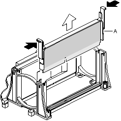
- Press the latches on the termination card (A) inward to release it from
the retention mechanism.
- Hold the termination card by its top edge and carefully rock it back and
forth until the edge connector pulls free from the Slot 1 connector.
 
To Install the Termination Card
If you remove the application processor you need to install the
termination card before you can turn the computer back on:
- Take suitable anti-static precautions.
- Turn off the computer, disconnect the computer’s power cord, and
disconnect all external peripherals.
- Remove any peripherals that block access to the application processor
Slot 1 connector.
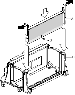
- Slide the termination card (A) into the retention mechanism (C). Ensure
that the alignment notch (B) in the termination card fits over the key in the application
processor Slot 1 connector.
- Press down firmly on the termination card until it is seated in the
Slot 1 connector and the latches on the termination card lock into place.
 
To Install a Second Processor
To install the second, or application processor, you must ensure that
the second processor is identical to the first processor, (see the warnings and guidelines
on page 6 of this chapter) if it is:
- Take suitable anti-static precautions.
- Turn off the computer, disconnect the computer’s power cord, and
disconnect all external peripherals.
NOTE:
The second processor must be identical in speed and voltage to the first processor. The
second processor also must be the same stepping as, or no more than one stepping higher
than, the first processor.
- Remove any peripherals that block access to the application processor
Slot 1 connector.
- If a termination card is installed in the application processor Slot 1
connector, remove it. See "How to Remove The Termination Card".
- Remove the processor from its antistatic package.
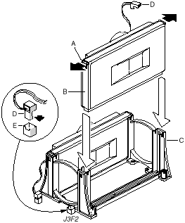
- Orient the processor (B) so that the heatsink faces the back of the
motherboard. Slide the processor into the retention mechanism (C). Ensure that the
alignment notch in the S.E.C. cartridge fits over the key in the Slot 1 connector.
- Press down firmly on the processor until it is seated in the
application processor Slot 1 connector and the latches (A) on the processor lock into
place.
- Processors supplied to you by Mitsubishi will have a standard heatsink.
However if your upgrade processor has a fan attached, connect the small end of the power
cable to the fan connector on the S.E.C. cartridge, then attach the large end (D) to the
CPU 2 fan connector (E) on the motherboard. The fan connectors are keyed so they will only
connect one way.
- Replace any peripherals that were removed in Step 3.
- Set the processor speed. See "To Set the
Processor Speed" for instructions.
 
To Set the Processor Speed
Set the processor speed after you have installed or upgraded the
processor. This procedure assumes that the computer is turned off, the cover is off, and
the configuration jumper block (J7E1) has the jumper set on pins 1-2 for normal mode.
- Take suitable anti-static precautions.
- Locate the configuration jumper block J7E1 from the illustration
of the motherboard.
- Move the jumper to pins 2-3 as shown below to set configure
mode.

- Replace the computer cover, turn on the computer, and allow it to boot.
- The computer starts the Setup program. Setup displays the Maintenance
menu.
- Use the arrow keys to select the Processor Speed feature and press
<Enter>. Setup displays a popup screen with the available processor speeds.
- Use the arrow keys to select the processor speed.
For example, select 266 for a 266 MHz PentiumŽII processor. Press <Enter>
to confirm the speed. The Maintenance menu reappears.
- Press <F10> to save the current values and exit Setup.
- Turn off the computer.
- Remove the computer cover.
- On the jumper block (J7E1), move the jumper back to pins 1-2 to restore
normal operation as shown below.

- Replace the cover and turn on the computer.
 

|


