 |


|
|
FT5000 - Access Cover &
Internal ViewAccess Cover
Removing the Access Cover
You need to remove the system access cover, and in some cases the front bezel, to
reach components inside the system. Facing the front of the system, the access cover is on
the right side for pedestal-mounted (tower) servers, and on the top for rack-mounted
servers.

- Observe the precautions as given in Safety & Regulatory Notices
at the front of the Owner's Handbook.
- Turn off and disconnect all peripheral devices connected to the
system.
- Turn off the system by using the power on/off switch on the front panel
AND unplug all AC power cords.
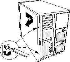
- Remove and save the two screws from the back of the access cover; you
will need them later to reattach the cover.
- Place the fingertips of your right hand under the built-in handle on the
back of the cover. A rounded, rectangular depression in the front middle of the access
cover serves as another handle.
- Using an even pull, slide the cover backward, about 2 to 3cm, until it
stops.
- Pull the entire cover outward, straight away from the chassis, to
disengage the rows of tabs from the notches in the top and bottom edges of the chassis.
Set the cover aside.
Installing the access cover
- Before replacing the access cover, check that you have not left loose
tools or parts inside the system.
- Check that cables, add-in boards, and other components are properly
installed.
- Position the cover over the chassis so that the rows of tabs align with
slots in the chassis. Slide the cover toward the front of the system until the tabs on the
cover firmly engage in the chassis.
- Attach the cover to the chassis with the two screws you removed earlier,
and tighten them firmly.
- Connect all external cables and the power cords to the system.
 
Subchassis and electronics bay
The chassis is comprised of three parts: the main
chassis, a swing-out subchassis at the front, and a swing-out subchassis, called the
electronics bay, at the rear. To access components in some instances, you must swing away
and/or completely remove the subchassis and electronics bay.

Observe the precautions as given in Safety & Regulatory
Notices at the front of the Owner's Handbook.
- Turn off and disconnect all peripheral devices connected to the
system.
- Turn off the system power by using the power on/off switch on the front
panel AND unplug all AC power cords.
- Remove and save the two screws from the back of the access cover; you
will need them later to reattach the cover.
- Remove the access cover.
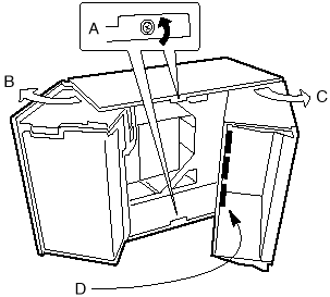
- Loosen screws on the top and bottom edges of the chassis (A) in the
illustration above. These screws attach the front subchassis and the electronics bay to
the main chassis.
Warning
You must disconnect all cabling to the electronics bay before rotating/removing the
bay. Failure to do so can result in serious damage to system components. The location of
the main connectors in the electronics bay is marked as D in the illustration above.
- Rotate the front subchassis left, away from the main chassis, until it
stops (B).
- Disconnect all cabling to the electronics bay (D).
- Using the vertical edge of the electronics bay as a handle, rotate the
bay right, away from the main chassis, until it stops (C).
- If necessary, completely remove the subchassis and electronics bay:
rotate the bays outward until the two pins that function as hinges for the bays slide out
of their slots.
 

|

