 |


|
|
FT5000 - Front, Back &
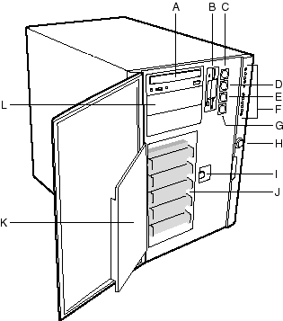
Side ViewsFront View

|
| Key |
Decription |
| A |
External drive bays; CD-ROM drive shown installed |
| B |
Diskette drive |
| C |
Power On/Off button (holding down this button for
more than four seconds causes a power-button override to the PIIX4E when you release the
button) |
| D |
Sleep/Service button (holding down this button for
LESS THAN four seconds enters sleep mode, which requires an ACPI-compliant OS; holding it
down for MORE THAN four seconds enters service mode, which powers down the electronics bay
but leaves hot-swap and peripheral bays running) |
| E |
Reset button |
| F |
Front panel LEDs (Top to bottom: top five are power
on, disk bay power on, HDU activity, fan failure, power supply failure; bottom six are
hard-drive activity LEDs, labeled 0-5) |
| G |
NMI button |
| H |
System security lock |
| I |
EMI shield lock |
| J |
Internal drive bays |
| K |
Metal EMI shield |
| L |
Expansion drive bay |
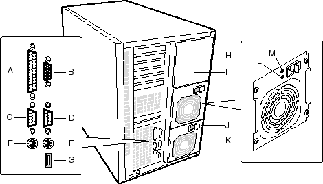
Rear View

|
| Key |
Decription |
| A |
Parallel port |
| B |
VGA monitor connector |
| C |
Serial port A, COM1 |
| D |
Serial port B, COM2 (extended via ribbon cable from
back panel to baseboard) |
| E |
Mouse connector |
| F |
Keyboard connector |
| G |
Universal serial bus connector |
| H |
Expansion slot covers (six slot connectors provided
on baseboard) |
| I |
Power supply bay |
| J |
AC input power connector |
| K |
Power supply fan |
| L |
Power supply LED |
| M |
Power supply failure LED (LED not lit means failure) |
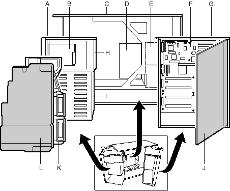
Expanded Side View

|
| Key |
Decription |
| A |
Front swing-out subchassis |
| B |
Diskette drive |
| C |
Main chassis |
| D |
Power backplane |
| E |
Power supply(s) |
| F |
Mainboard |
| G |
Lift-out electronics bay |
| H |
Removable media device bay |
| I |
SCSI hard drive bay |
| J |
Foam cover |
| K |
Foam fan housing |
| L |
Foam fan housing cover |
 

|

