Conner CTL96GR-S Autoloader
 
Specification
| Apricot Part Number |
PT15355031 |
| Form Factor |
5.25-inch x full height |
| Error Rate |
Less than 1 in 1015 bits |
| Controller Interface |
SCSI II |
| Transmission |
Single ended, asynchronous or synchronous |
| Media |
4GB DDS Tape 120metre (five) XB55638 |
 
Drive Performance
| Capacities (120 Metre Tape) |
Native |
16 GB |
| Compressed |
32 GB |
| Data Transfer Rate |
Native |
400 KB/sec |
| Compressed |
800 KB/sec |
| Burst Rate |
5 Mb/sec |
| Tape Speed |
0.47 inches/sec |
| 11.9 mm/sec |
| Head to Tape
Speed |
270 inches/sec |
| 6.858 mm/sec |
| Search/Rewind |
200 x normal speed |
| Average Access Time |
90 Metre Tape |
30 seconds |
| 120 Metre Tape |
40 seconds |
| Buffer |
1 MB |
| EEPROM |
Flash |
| Recording Method |
Helical Scan (R-DAT) |
| DDS-2 ANSI/ECMA |
| DDS-DC |
 
Environment
|
Operating |
Non-operating |
| Temperature |
41º to 113º F (5º to 45º C) |
-40º to 149º (-40º to 65º C) |
| Relative Humidity |
20% to 80% non condensing |
|
| Wet Bulb Temperature |
78.8º F (26º C) |
|
| MTBF (20% Duty Cycle) |
125,000 hours |
|
| MTTR |
Less than 30 minutes |
|
| Power
Requirements |
+5V |
2.2 A typical |
| +12V |
1.7 A typical |
| Watts |
29W for loader typical |
| Dimensions |
Form Factor |
5.25" FH |
| Height |
3.2" (82mm) |
| Width |
5.7" (146mm) |
| Length |
8.0" (203mm) |
| Weight |
|
 
Dimensions
| Form Factor |
5.25" HH |
|
| Height |
1.7" |
43mm |
| Width |
5.8" |
147mm |
| Length |
7.1" |
180mm |
| Weight |
1.6lbs |
0.7Kg |
 
Jumpers

SW1—Configuration Switches
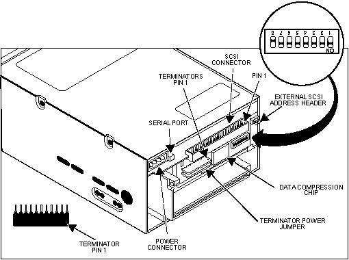
Set the configuration switches. SW1 switches 1 through 8 can be accessed
through the cutout at the rear of the unit where the step-down occurs. (Figure 1) Figure 2
shows the default settings for the Autoloaders for these switches on SW1 (view looking
from the rear of the unit down into the cutout) and illustrates the switch settings for
selecting the SCSI address.

Note: .The drive must be turned OFF; then, ON in order for switch
settings to take effect, or a SCSI bus reset must be received.
SCSI Device Address (S1 through S3)
The three switches S1 through S3 correspond to the SCSI device address
identification bits 0 (LSB) through 2 (MSB), respectively, which provides the SCSI ID. The
default setting is SCSI device address 0 (S1 through S3 = OFF). Be sure that no other
device on the SCSI bus has the same SCSI address. The Autoloader uses a single SCSI ID.
Media Recognition System (MRS) (S4)
The S4 switch enables or disables Media Recognition System (MRS) mode.
The default is MRS disabled (S4 = ON). If S4 is ON, the drive reads or writes both MRS and
non-MRS 4-mm media.
If S4 is OFF, the drive only writes to MRS media. The drive reports a
check condition if the media is nondata grade, and the Sense key will be 07, Data Protect.
The additional Sense Code and qualifier will be 30/00, Incompatible Media Installed. The
drive reads any kind of 4-mm media when S4 is OFF.
S4 = ON disables MRS
S4 = OFF enables MRS
Parity Enable/Disable (S5)
The S5 switch enables or disables parity and checking for the SCSI bus.
The default is parity disabled (S5 = OFF).
S5 = ON enables parity checking
S5 = OFF disables parity checking
DDS Pass-Through Mode Enable/Disable (S6)
The S6 switch enables or disables DDS pass-through mode. The default is
DDS pass-through mode disabled (S6 = OFF).
S6 = ON enables DDS pass-through mode S6 = OFF disables DDS pass-through
mode
Note: When S6 is OFF, DDS-DC data compression is enabled during writing.
When S6 is ON, DDS-DC data compression is disabled. When being read by the Autoloader,
DDS-DC compressed data is always decompressed, regardless of the position of S6.
The function of the S6 switch can be overridden by the proper SCSI MODE
SELECT command issued from the host computer. Regardless of the position of S6, the MODE
SELECT command can enable or disable data compression.
Reserved Switch (S7)
The S7 switch is reserved and should be left in its factory default
setting.
Power-on Self-Test Mode Enable/Disable (S8)
The S8 switch enables or disables execution of power-on self-test
diagnostics when the power comes ON. The default is power-on self-test mode disabled (S8 =
OFF). If ON, the drive responds to SCSI commands after successful completion of the test
(about 5 seconds). S8 = ON enables power-on self-test mode.
 

|

