System Unit
ConnectorsPinouts and connector diagrams for the
commonly used connectors in the Apricot product range, both past and present. Browse
through the page to see what's available or click on one of the connectors in the list
below to go straight to the one you are interested in.
Video Connector
 |
| Pin |
Output |
Mono |
Colour |
| 1 |
Red |
No Pin |
Red |
| 2 |
Green |
Mono |
Green |
| 3 |
Blue |
No Pin |
Blue |
| 4 |
Reserved |
No Pin |
No Pin |
| 5 |
Digital G |
Self Test |
Self Test |
| 6 |
Red Return |
Key Pin |
Red Return |
| 7 |
Green Return |
Mono Return |
Green Return |
| 8 |
Blue Return |
No Pin |
Blue Return |
| 9 |
Plug |
No Pin |
No Pin |
| 10 |
Digital G |
Digital G |
Digital G |
| 11 |
Reserved |
No Pin |
Digital G |
| 12 |
Reserved |
Digital G |
No Pin |
| 13 |
Horizontal Sync |
Horizontal Sync |
Horizontal Sync |
| 14 |
Vertical Sync |
Vertical Sync |
Vertical Sync |
| 15 |
Reserved |
No Pin |
No Pin |
|
 
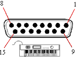
Serial Port 9 pin
 |
| Pin |
Signal Name |
Input / Output |
| 3 |
Transmit Data |
Output |
| 2 |
Receive Data |
Input |
| 7 |
Request To Send |
Output |
| 8 |
Clear To Send |
Input |
| 6 |
Data Set Ready |
Input |
| 5 |
Ground |
N/A |
| 1 |
Data Carrier Detect |
Input |
| 4 |
Data Terminal Ready |
Output |
| 9 |
Ring Indicator |
Input |
|
 
Serial Port 25 pin
 |
| Pin |
Signal Name |
Input / Output |
| 2 |
Transmit Data |
Output |
| 3 |
Receive Data |
Input |
| 4 |
Request To Send |
Output |
| 5 |
Clear To Send |
Input |
| 6 |
Data Set Ready |
Input |
| 7 |
Ground |
N/A |
| 8 |
Data Carrier Detect |
Input |
| 20 |
Data Terminal Ready |
Output |
| 22 |
Ring Indicate |
Input |
|
 
Dual Serial Port
 |
| Pin |
I/O |
Function |
Pin |
I/O |
Function |
| 1 |
NA |
Not connected |
13 |
NA |
Clear to Send COM 2 |
| 2 |
Output |
Transmit Data COM 1 |
14 |
NA |
Transmit Data COM 2 |
| 3 |
Input |
Receive Data COM 1 |
15 |
NA |
Transmit Clock |
| 4 |
Output |
Request to Send COM 1 |
16 |
NA |
Receive Data COM 2 |
| 5 |
Input |
Clear to Send COM 1 |
17 |
NA |
Receive Clock |
| 6 |
Input |
Data Set Ready COM 1 |
18 |
NA |
Request to Send COM 2 |
| 7 |
NA |
Signal Ground |
19 |
NA |
Not connected |
| 8 |
Input |
Data Carrier Detect COM 1 |
20 |
Output |
Data Terminal Ready COM 1 |
| 9 |
NA |
Not connected |
21 |
NA |
Not connected |
| 10 |
NA |
Not connected |
22 |
Input |
Ring Indicate COM 1 |
| 11 |
NA |
Not connected |
23 |
NA |
Not connected |
| 12 |
Input |
Data Carrier Detect COM 2 |
24 |
NA |
Not connected |
|
25 |
NA |
Not connected |
 
Parallel Port
 |
| Pin |
Input/Output |
Signal Name |
Pin |
Input/Output |
Signal Name |
| 1 |
Input/Output |
Strobe |
10 |
Input |
Acknowledge - |
| 2 |
Input/Output |
Data bit 0 |
11 |
Input |
Busy |
| 3 |
Input/Output |
Data bit 1 |
12 |
Input |
PE |
| 4 |
Input/Output |
Data bit 2 |
13 |
Input |
SLCT |
| 5 |
Input/Output |
Data bit 3 |
14 |
Output |
Autofeed XT - |
| 6 |
Input/Output |
Data bit 4 |
15 |
Input |
Error - |
| 7 |
Input/Output |
Data bit 5 |
16 |
Output |
Initialise - |
| 8 |
Input/Output |
Data bit 6 |
17 |
Output |
SLCT in - |
| 9 |
Input/Output |
Data bit 7 |
18 - 25 |
NA |
Ground |
 
Joystick / MIDI Port
 |
| Pin |
Input/Output |
Function |
| 1 |
NA |
+5V dc |
| 2 |
Input |
Joystick/A Right Button |
| 3 |
Input |
Joystick/A X-Coordinate |
| 4 |
NA |
Ground |
| 5 |
NA |
Ground |
| 6 |
Input |
Joystick/A Y-Coordinate |
| 7 |
Input |
Joystick/A Left Button |
| 8 |
NA |
+5V dc |
| 9 |
NA |
+5V dc |
| 10 |
Input |
Joystick/B Right Button |
| 11 |
Input |
Joystick/B X-Coordinate |
| 12 |
Output |
MIDI Out |
| 13 |
Input |
Joystick/B Y-Coordinate |
| 14 |
Input |
Joystick/B Left Button |
| 15 |
Input |
MIDI In |
|
 
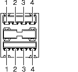
Universal Serial Bus (USB) Dual Port
 |
| Pin |
Input/Output |
Function |
| 1 |
- |
+ 5 Vdc |
| 2 |
Bi directional |
Data - |
| 3 |
Bi directional |
Data + |
| 4 |
- |
Ground |
|
 
Keyboard / Mouse Port
 |
| Pin |
Input / Output |
Signal Name |
| 1 |
Input/Output |
Data |
| 2 |
NA |
Reserved |
| 3 |
NA |
Ground |
| 4 |
NA |
+5V DC |
| 5 |
Input/Output |
Clock |
| 6 |
NA |
Reserved |
|
 
Qi / Panther Power Connector
 |
| Pin |
Function |
Colour |
| 1 |
+5V |
Yellow |
| 2 |
0V |
Black |
| 3 |
+12V |
Red |
| 4 |
+5V |
Yellow |
| 5 |
0V |
Black |
| 6 |
Power Good |
Orange |
| 7 |
+5V |
Yellow |
| 8 |
0V |
Black |
| 9 |
0V |
Black |
| 10 |
+5V |
Yellow |
| 11 |
0V |
Black |
| 12 |
-12V |
Grey |
|
 
LS Pro (Bonsai) Power Connector
 |
| Pin |
Function |
Colour |
| 1 |
+12V |
Yellow |
| 2 |
+12V |
Yellow |
| 3 |
+5V |
Red |
| 4 |
+5V |
Red |
| 5 |
0V |
Black |
| 6 |
0V |
Black |
| 7 |
0V |
Black |
| 8 |
0V |
Black |
| 9 |
-12V |
Blue |
| 10 |
Power Good |
Orange |
|
 
Motherboard Power Connector
 |
| Pin |
Function |
Colour |
| 1 |
Power Good |
White |
| 2 |
+5V |
Red |
| 3 |
+12V |
Orange |
| 4 |
-12V |
Blue |
| 5 |
0V |
Black |
| 6 |
0V |
Black |
| 7 |
0V |
Black |
| 8 |
0V |
Black |
| 9 |
-5V |
Yellow |
| 10 |
+5V |
Red |
| 11 |
+5V |
Red |
| 12 |
+5V |
Red |
|
 

|

