Apricot and RAID RAID was originally an acronym for Redundant Array of Inexpensive Disks. Each
RAID level describes the method in which data is distributed across a number of disk
drives, known as an array. It must be noted however, that these are not true
"levels", as the higher levels don't contain all the functions of the lower
levels, and RAID 5 is not necessarily better than RAID 3.
The birth of drive arrays effectively started with a paper published by
Berkeley University (CA), this paper classified the different architectures as RAID
levels. The driving force was to provide minicomputers with high performance drive
subsystems using the (then) newly available low cost 5.25" Winchesters rather than
the very expensive mass storage magnetic drives used by mainframes. The concept was to
provide the required capacity using multiple 5.25" drives connected as an array; in
effect the drives were operated in parallel to increase their performance.
The word 'Inexpensive' in RAID's original definition is now somewhat of
a misnomer. The drives used in a RAID solution tend to be high quality, fast, SCSI devices
which are by no means the cheapest drives available for PCs. Consequently, the definition
of RAID is undergoing a change from Redundant Array of Inexpensive Disks to Redundant
Array of Independent Disks.
 
RAID Levels
The original Berkeley paper described five RAID levels. Of these only
RAID 1, 3 and 5 are now considered practical solutions. RAID 2 and 4 have been superseded
by RAID 3 and 5 respectively as they offer similar or superior performance at no
additional cost.
There are other levels of RAID, but of these, only RAID 0 is accepted as
an industry standard.
Note: For the purpose of this document, the diagrams illustrate a RAID
solution using either two or four disk drives - this is not a mandatory requirement. Each
RAID solution should be tailored to the customer's application using the appropriate
number of drives.
RAID LEVEL 0
RAID 0 was not described by the Berkeley team but due to its wide
availability has since been endorsed by the RAID Advisory Board (RAB). RAB is an
association of suppliers and consumers of RAID related products and other organisations
with an interest in RAID technology set up to standardise RAID related terminology
throughout the industry.

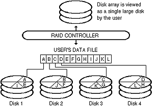
RAID 0, also known as disk striping, works by segmenting a user file
into 'data blocks' and then writing the blocks sequentially across the drives in the
array. Disk striping offers excellent performance by transferring data using several disks
at once. However, in this configuration only one copy of the data is stored, and therefore
no fault tolerance is achieved. In fact this method is even more open to data loss; when
four drives make up a single logical drive, that logical drive is four times more likely
to fail than a single physical disk. Strictly speaking RAID level 0 is not a RAID at all
as there is no redundancy.
RAID 0 can be implemented on any NetWare or Windows NT system with more
than 1 hard disk, without the introduction of any special hardware. Under NetWare this
option is called “Spanning a volume” and is achieved when creating a new volume
either at installation time or when adding another drive. Under Windows NT 3.5 this is a
standard feature of the Disk Administrator and is called “Create Stripe Set”.
RAID LEVEL 1
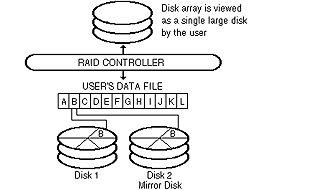
RAID 1 is also known as mirroring or shadowing. In its simplest form two
disks are connected to a single controller, and as data is written to one disk the same
information is also written to the mirrored disk.

If one drive fails, the system continues to run using data from the
remaining drive. However, if the controller fails, both drives fail and the system is
down. To overcome this, two controller cards can be used, which is a method known as
duplexing.
The biggest disadvantage of mirroring is its cost. With each active
drive duplicated exactly, there is 50 percent data redundancy and twice the cost of the
same system with no mirroring.
Again, RAID 1 can be implemented on any NetWare or Windows NT system
with more than 1 hard disk, without the introduction of any special hardware.
RAID LEVEL 3
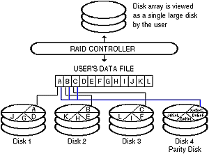
RAID 3 employs a technique called 'disk striping with redundancy'. This
offers the advantage of disk striping but without the very high level of data redundancy
and cost of mirroring.

It provides data redundancy by producing 'parity' data that is stored on
a dedicated drive referred to as the parity drive. Parity data is created by applying
complex mathematical calculations to the original data which extract relevant bits of
information that can be stored using a fraction of the space used by a mirror image. In
the event of a drive failure, this parity information can be used to reconstruct the
original data.
The disadvantage with this technique is that every time a write occurs,
parity information must be stored to a single disk. The idea of introducing
“Striping” is so that when a system is under heavy load, the writes are spread
across a number of drives in parallel, implementing RAID 3 therefore reduces the
performance of the system by having only a single drive for parity.
RAID LEVEL 5
RAID 5 combines data striping and the storing of parity data on all
drives, as opposed to one dedicated parity drive. This option requires a minimum of three
hard disk drives.

RAID 5 and RAID 3 are very similar in terms of the benefits they offer,
their cost implications and the way in which they function. However, there are some
fundamental differences that make them suitable for very different applications. The
process of storing parity data across a number of drives, rather than one dedicated parity
drive, alleviates the bottleneck created by many parity write requests being directed to
one drive.
In a RAID 5 configuration the amount of data actually stored on each
individual drive during the data striping process is larger than in RAID 3. Consequently
requests are typically serviced from one drive, as opposed to several drives, and thus the
potential competition for access to one drive is minimised. Due to this process RAID 5 is
particularly effective for applications which access a high number of small files such as
large databases and transaction processing systems (which most network users will be
running). In contrast, RAID 3 is particularly effective for applications such as image
processing which access large files.
OTHER RAID LEVELS
Many RAID products available today use RAID levels other than the
standard ones in their names or descriptions, e.g. RAID 6, RAID 8 etc. Usually these are a
combination of the levels described above, or the subsystem that implements one of these
may have been enhanced with a feature such as a cache. Of these non-standard levels, RAID
6 and RAID 10 are more widely used than any others.
RAID LEVEL 6
RAID 6 is very similar to RAID 5, except that it stores two copies of
the parity data rather than one, with each copy being written to a separate drive. This
feature significantly improves reliability as three disks in the array must fail for data
to be lost; however, the write performance is the lowest of all RAIDs.
RAID LEVEL 10 (1/0)
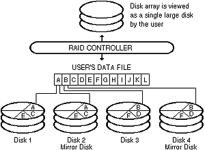
Level 10, usually pronounced "one zero", combines the features
of RAID level 0 (striping) and RAID level 1 (mirroring) to produce a system with very high
performance and high data reliability, but at a relatively high cost.

It should be noted that some manufacturers use the term RAID 6 to define
the combination of RAID 0 & 1.
 
The Apricot Implementation
Apricot have introduced this feature into the standard FT//ex 1000,
renaming it the FT//ex 1000R. This system employs a very high performance RAID controller
from a company called DPT which initially provides a high speed 32 bit PCI local bus
adapter with a single channel, 10MB/s SCSI controller and 4Mb of high speed cache.
CHANGES TO THE FT//ex 1000
The SCSI cable is replaced by a PCB backplane that allows up to 3 SCSI
channels to be fed to the 8 drive bays in the FT//ex. This board provides both a path for
the SCSI, the connectors to “hot swap” SCSI devices and switchable terminators
that allow a flexible combination of either 1, 2 or 3 channel SCSI.
Each of the eight drive trays have extra fittings applied that allow the
drive tray to be locked in place and the drive to be powered down to initiate a “hot
swap” of a faulty drive. In addition an LED shows when the drive is correctly
powered.
The on-board Adaptec AIC7870 SCSI controller is employed to control the
CD ROM drive and any tape devices fitted in the system while the DPT RAID controller
handles the hard disk drives. We would always recommend this configuration as the handling
of removable media devices on a RAID controller over-complicates the configuration whilst
not providing any advantages over using the on-board controller.
Apricot sell systems with 4, 1Gb IBM “Pegasus” drives
installed. This is what is considered the optimum configuration for RAID 5 as it allows
the use of 3 of the hard disks to be employed as a RAID 5 system and the fourth drive to
be as a “hot standby” drive.
HOT SWAP
Hot Swap is not a facility offered by RAID but is dependant upon the
server itself. It requires the ability to power down each hard disk drive independently
without shutting down the server. Once the drive is powered down then the drive can be
removed without putting too much electrical interference on the, still active, SCSI bus.
On the FT//ex 1000R this is achieved by replacement drive trays that
include both a power switch for each drive and a PCB edge connector with staggered
power/ground/data lines that connect smoothly into the Backplane.
HOT STANDBY
This is a facility provided by the RAID controller card. If an
additional disk is placed on the SCSI bus but is not used for any data, then in the event
of one of the other drives failing, the data and parity information is recreated onto the
“spare” drive thus allowing for more than one drive to fail without data loss.
THE DPT PM3224 SmartRAID CONTROLLER
This is a full length, 32 bit PCI 2.0 local bus card containing a 68030
40MHz processor to give full 132MByte/s PCI bus mastering. It supports full SCSI-2
initially on a single channel with the option to upgrade to 2 or even 3 channels. The DPT
card will support RAID levels 0, 1 and 5 (not RAID 3).
Cache starts with a single 4MB SIMM and is upgradeable to a full 64MB
via 72 pin, 36 bit SIMMs with ECC parity. The board has 4 SIMM sockets which will accept
either 4MB or 16MB each, allowing a wide range of upgrade options without wasting SIMMs
that you have already purchased.
The card also includes on-board sensors for temperature and voltage
fluctuations and is upgradeable to wide SCSI-2.
Shipped with the card are drivers for NetWare 3.x, 4.x, IBM OS/2, SCO
UNIX, Microsoft OS/2 1.x, Windows NT, Banyan VINES, UnixWare and many more. With some of
these environments it is possible to make changes to the system from a remote site using
DPT's Storage Manager software.
In the event of a disk failure, it is possible to both log any events as
well as broadcast a message to all users or selected groups informing them of any fault in
the system, whilst the server continues to run unaffected. Connections can also be made
via modem and notifications can be passed via pager or fax.
 
Warning!
With RAID hardware and software installed, it is possible to continue
normal operation in the event of a disk failure and with Apricot’s FT//ex 1000R it is
possible to rectify faults without downing the server.
However, in any RAID scenario, whilst the system is running in
“degraded” mode (ie. one of the disks has failed and it has not yet updated any
hot spare drives that may be available) switching off the wrong drive can cause data loss.
It is vital that all hardware engineers who may need to change drives in
a RAID system have training on what effects removing the wrong drive can have.
Apricot will run a number of seminars explaining RAID further and
helping you to recommend just how many drives and in what configuration they are best
installed.
 
Questions and Answers
- What does RAID stand for?
- RAID stands for Redundant Array of Inexpensive Disks, or more recently
Redundant Array of Independent Disks
- Why is RAID beneficial?
- It can provide an increased degree of fault tolerance to prevent loss of
information in the event of a failure of the storage sub-system.
- Are there different types of RAID implementation?
- There are 6 main types of RAID, known as levels 0 to 5, although in
practice only levels 0, 1, 3, and 5 are used.
- Is one particular type of RAID best?
- The simple answer is 'no'. The most suitable implementation depends on
the type of data that is likely to be processed.
- Which RAID implementation is best for each type of data?
- In general RAID 0 is used where speed is the only consideration as no
redundancy is provided. RAID 1 is excellent where the need for reliability and speed are
paramount; however, the cost of data storage cannot be a consideration since the amount of
disk space is doubled. RAID 5 is best where there are small files with a lot of disk I/O
such as large databases or transaction processing systems.
 

|

