LS Pro (Caracal)
Motherboard Layout (Rev 1.5.1)
 
RAM Configurations
On-Board |
SIMM 1 |
SIMM 2 |
Total |
4 Mb |
- |
- |
4 Mb |
4 Mb |
4 Mb |
- |
8 Mb |
4 Mb |
4 Mb |
4 Mb |
12 Mb |
4 Mb |
8 Mb |
- |
12 Mb |
4 Mb |
8 Mb |
4 Mb |
16 Mb |
4 Mb |
8 Mb |
8 Mb |
20 Mb |
4 Mb |
16 Mb |
- |
20 Mb |
4 Mb |
16 Mb |
4 Mb |
24 Mb |
4 Mb |
16 Mb |
8 Mb |
28 Mb |
4 Mb |
16 Mb |
16 Mb |
36 Mb |
4 Mb |
32 Mb (See Note) |
- |
36 Mb |
4 Mb |
32 Mb (See Note) |
4 Mb |
40 Mb |
4 Mb |
32 Mb (See Note) |
8 Mb |
44 Mb |
4 Mb |
32 Mb (See Note) |
16 Mb |
52 Mb |
4 Mb |
32 Mb (See Note) |
32 Mb (See Note) |
68 Mb |
Memory Expansion consists of
two 72-pin SIMM sockets, no parity, 70ns or faster. |
Memory Expansion Note
For the correct operation of this device in Caracal and to gain the best
system performance, this device is to be ONLY used in Caracal systems with a Cache Module
installed. Its use in cacheless machines is NOT recommended.
 
Ethernet Options
| Ethernet AMD PCNet-32 |
| Controller 32-bit VL local bus master controller |
|
| Interfaces |
| UTP RJ-45 connector on motherboard (10Base-T) |
| Thin Wire On-board shielded BNC connector (10Base-2) |
| Thick Wire Connector via 16 way IDC header (10Base-5) |
|
| PCMCIA Token Ring card XB53637 |
 
Disk Drives
 
Switch Settings
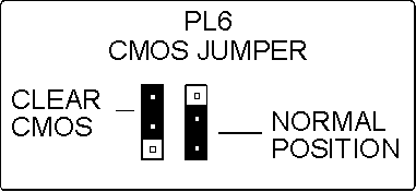
PL6 CMOS Jumper
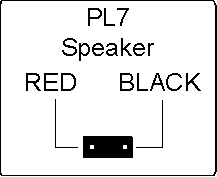
PL7 Speaker
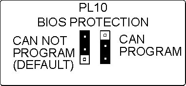
PL10 BIOS Protection
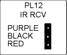
PL12 IR Receive
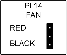
PL14 Fan
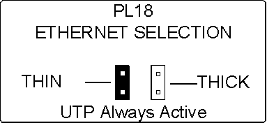
PL18 Ethernet Selection
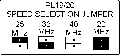
PL19 / 20 Speed Selection Jumper
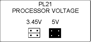
PL21 Processor Voltage
Do not alter from default position
PL23 Processor Voltage
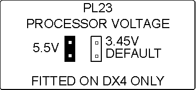
Do not alter from default position
PL24 Processor Voltage
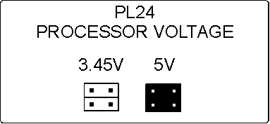
Do not alter from default position
PL25 Processor Jumper
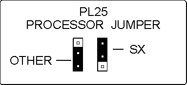
 
Additional Options
| Other Memory Expansion |
|
| 256Kb Cache RAM upgrade |
BP53934 |
|
|
| Modems |
|
| PCMCIA fax/modem card |
XB53638 |
 
Rear Panel
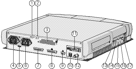
| 1 - Security Loop |
2 - Security loop |
3 - PCMCIA Slots |
| 4 - Power Out |
5 - Voltage Switch |
6 - Power In |
| 7 - Serial Port |
8 - Parallel Port |
9 - VGA Port |
| 10 - UTP Connector |
11 - Thick Ethernet |
12 - Thin Ethernet |
| 13 - Mouse Port |
14 - Keyboard Port |
15 - Microphone Socket |
| 16 - Headphone Socket |
17 - Volume Switch |
|
 
CMOS Discharge

To enter CMOS SETUP press ALT-S key
combination when invited to do so at boot up.
 
Basic Configuration
Options
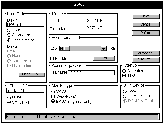
 
Hard Disk
The disk 1 information box shows the type and capacity of the computer's
fixed hard disk drive, where known. Beneath this are three option buttons:
| Option |
Description |
| None |
Select this if your computer does not have a fixed hard
disk. This prevents the BIOS looking for a hard disk, and so speeds up the boot sequence. |
| Autodetect |
Select this if your computer has a hard disk drive
supplied by Apricot. In this case the BIOS will be able to detect the drive type
automatically. |
| User-defined |
Select this if your computer has a third-party hard disk
drive not supplied by Apricot. You must then define the characteristics of the drive. |
To define a Third-party hard disk drive:
 
User
Defined Hard Disks
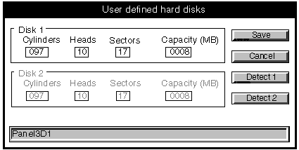
In the User-defined Hard Disks dialog box, choose the
Detect button to see if BIOS Setup can detect what type of drive is fitted. If it can,
then the characteristics of the drive appear in the dialog.
If BIOS Setup cannot detect the drive type, you must
manually enter the drive's number of cylinders, heads and sectors, and its capacity, in
the text boxes provided.
Choose the Save button.
 
Floppy Disk
The information box shows the type and capacity of the computer's
diskette drive. Beneath it are two option buttons:
| Option |
Description |
| None |
Select this if your computer does not have a diskette
drive. This prevents the BIOS looking for a system diskette, and so speeds up the boot
sequence. |
| 3.5" 1.44M |
Select this if your computer has a 1.44 Mbyte diskette
drive. |
 
Memory
These information boxes show the total amount of system memory
(motherboard memory plus any additional memory modules, minus the 384 Kbytes upper memory
area) and the amount of extended memory (total memory minus the 640 Kbytes of conventional
memory).
 
Power-on
Sound
When this option is enabled a tone will sound whenever the computer is
turned on.
To set the power-on sound:
- In the Power-on Sound group, select the Enable check box.
- Choose the Test button to audition the Power-on sound.
- Use the scroll bar to adjust the volume of the Power-on sound as
required.
 
Power-on
Password
If this option is enabled a password must be entered every time the
computer is turned on.
To set a power-on password:
- In the Power-on Password group, select Enable check box.
- Select the text box, and type a password of up to seven characters using
A-Z and 0-9. The password is not case-sensitive and cannot include space characters. To
preserve security, the password is not displayed as you type but is shown as a string of
asterisks.
The power-on password operates in addition to the security system
features, if enabled.
 
Monitor
Type
These three options alter the timings of the video signals provided by
the computer to suit a variety of different types of monitor.
It is important that you make the correct selection for your monitor.
See the Apricot Help on the on-board EVGA controller for up-to-date advise on the choices
to make for Apricot monitors.
| Option Resolution and refresh rates |
| SVGA |
640 x 480 @ 60 Hz |
|
800 x 600 @ 56 Hz |
|
1024 x 768 @ 87 Hz Interlaced |
| VGA/EVGA |
640 x 480 @ 60 Hz |
|
800 x 600 @ 60 Hz |
|
1024 x 768 @ 60 Hz |
| EVGA (high refresh) |
640 x 480 @ 72 Hz |
|
800 x 600 @ 72 Hz |
|
1024 x 768 @ 70 Hz |
|
1280 x 1024 @ 60 Hz |
 
Startup
The Startup options control how the display looks during POST, when BIOS
sign-on and hardware configuration messages are displayed.
| Option |
Description |
| Graphics |
During POST, a dialog box is displayed giving information
about your computer, including the BIOS version, type of video controller and Ethernet
node address. The dialog includes a Setup button for accessing BIOS Setup. |
| Text |
The same information is displayed, but using only text. A
message invites you to "Press Alt-S for SETUP". |
 
Boot Device
These options allow you to select where you want the computer to look
for an operating system when it boots.
Remote or network booting using Ethernet RPL won't work unless there's
an RPL server somewhere in your network. Don't attempt to boot your computer in this way
without first checking with the network administrator.
| Option |
Description |
| Local |
The computer looks for a system diskette or a bootable
hard disk partition (in that order). |
| Ethernet RPL |
The computer attempts to load an operating system from a
server elsewhere on the network, using the on-board Ethernet adapter and the Remote
Program Load (RPL) code in the BIOS ROM. |
| PCMCIA Card |
This option is provided for future development of BIOS
Setup; it is greyed-out in the current version. |
 
Advanced
Configuration Options
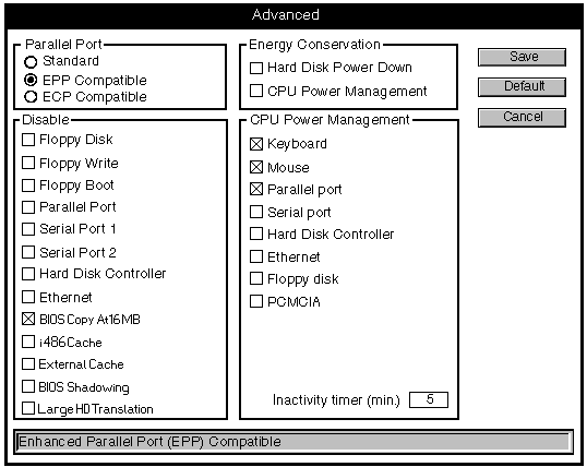
 
Parallel Port
These three options allow you to set the mode of the parallel port.
| Option |
Description |
| Standard |
Standard IBM AT-compatible bi-directional
"Centronics" mode. EPP Compatible Compatible with the Enhanced Parallel Port
standard. |
| ECP Compatible |
Compatible with the Microsoft/Hewlett Packard Extended
Capabilities Port standard. |
 
Disable
Floppy Disk
Disables the diskette drive controller.
 
Disable
Floppy Write
Disables the computer's ability to write to the diskette drive.
 
Disable
Floppy Boot
Disables the computer's ability to boot from a system diskette in the
diskette drive.
 
Disable
Parallel Port
Disables the parallel port, freeing interrupt IRQ7 and I/O ports
3BCh-3BFh. However, IRQ7 can usually be "double-booked" without affecting the
operation of the parallel port.
 
Disable
Serial Port 1
Disables serial port 1, freeing interrupt IRQ4 and I/O ports 3F8h-3FFh.
 
Disable
Serial Port 2
Disables serial port 2, freeing interrupt IRQ3 and I/O ports 2F8h-2FFh.
 
Disable
Hard Disk Controller
Disables the hard disk controller, freeing I/O ports 1F0h-1F8h and
3F6h-3F7h.
 
Ethernet
Disables the on-board network adapter, freeing interrupt IRQ5 and I/O
ports 300h-317h. (However, interrupt IRQ5, even if free, cannot be used by the PCMCIA
interface.)
 
Disable
BIOS Copy at 16MB
Disables the "copy" of the computer's BIOS ROM which normally
appears in the computer's address space just below 16Mbytes (between FE0000h and FFFFFFh).
This is not a real copy, just the same ROM addressed through a different (higher) set of
memory addresses. This copy must be disabled if your computer actually has 16Mbytes (or
more) system memory, or the two will conflict.
 
Disable
i486 Cache
Disables the memory cache inside the system processor.
 
Disable
External Cache
Disables the external, or second-level memory cache, outside the system
processor.
 
Disable
BIOS Shadowing
Disables the scheme whereby the contents of the computer's BIOS ROM are
copied into system memory, where they can be accessed more quickly.
 
Disable
Large HD Translation
Disables the scheme (known as Extended CHS) whereby the BIOS is able to
access hard disk drives of greater than 504 Mbytes capacity. You might need to do this if
your operating system does not support Extended CHS, in which case the drive will appear
to have less than its full capacity.
 
Energy
Conservation
Currently Unavailable
 
CPU Power
Management
Currently Unavailable
 

|


