The motherboards two DIMM sockets accept DIMMs of up to 128
Mbytes in any combination (giving a maximum memory capacity of 256 Mbytes)
Technical Note
The DIMMs you use must have the following specification: gold contacts, 3.3V, 64-bit,
unbuffered, SDRAM-type with Serial Presence Detect (SPD) and a CAS latency of 2 at 66 MHz.
If you use any other type of DIMM you risk damaging the motherboard.
On the motherboard, pin 1 of each jumper block is indicated by a small
triangular marking.
Do not change jumper settings unnecessarily
Do not alter any jumpers or switch settings other than those identified in this chapter,
unless told by your Mitsubishi Electric PC supplier or an authorised maintainer.
Otherwise, you may damage the system processor, the motherboard, or both.
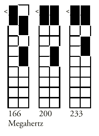
Processor bus speed (J10)
After upgrading your processor, but before turning on the system, you need to change some
jumper settings in jumper block J10 to match the speed (in megahertz) of the new
processor.

On-board video disabling (J50)
If you install a video adapter expansion card, the computer should automatically
detect this and disable the on-board video adapter. If for some reason this does not
happen, and you experience problems with a newly-fitted card, you can manually disable the
on-board video adapter by moving the jumper in block J50 to pins 2 - 3.
Audio disabling (J80)
The on-board audio codec can be disabled bt moving the jumpers on jumper block
J80 to pins 2 - 3. Disabling the audio system frees the interrupts and DMA channels used
by that system (normally IRQ5, IRQ11, DMA0 and DMA1).
Replacing the configuration battery
The computer keeps a record of its current hardware configuration in a CMOS memory chip
which is sustained by a small battery. This battery has a life of up to 5 years. If you
find that you have to reconfigure the computer every time you turn it on, the battery is
probably failing and needs to be replaced.
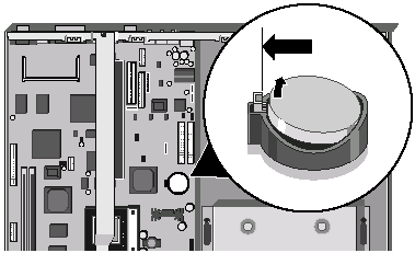
The battery is a 3 volt lithium type (CR2032 or equivalent) typically used in calculators
and other small, battery-powered electronic items.
To replace the battery
1. Turn off the computer and unplug all power cords.
2. Take suitable anti-static precautions and remove the system unit cover. For more
information see the section on "Anti-static precautions" in the Safety &
Regulatory Notices at the start of this manual.
3. Remove any expansion cards that impede access to the battery holder.
4. Using a non-conductive implement, release the latch that holds the battery in place.
The battery will pop up allowing you to lift it out of the holder.

Warning
You must not use a metal or other conductive implement to remove the battery. If a
short-circuit is accidentally made between the battery’s positive and negative
terminals, the battery may explode.
5. Check that the replacement battery looks the same as the battery you
have removed.
6. Taking care not to touch the top or bottom surface of the battery, pick up the
replacement with the positive (+) terminal upwards. Press the battery into the holder
using a non-conductive implement.
7. Replace any expansion cards you removed earlier and refit the system unit cover.
8. Dispose of the discharged battery in accordance with the battery manufacturer’s
instructions.
The next time you turn on the computer you will have to run the BIOS Setup utility to
reset the hardware configuration.


