'Spitfire'
Motherboard Layout
 
Front View
Mini-tower
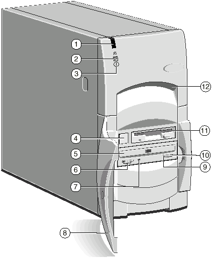 |
| 1 |
Infra-red sensor (optional) |
7 |
CD activity indicator |
| 2 |
Hard disk activity indicator |
8 |
Lockable front door |
| 3 |
Power Mode indicator |
9 |
CD emergency eject hole |
| 4 |
Power button |
10 |
CD Eject button |
| 5 |
CD-ROM disc drawer (platter) |
11 |
Diskette drive |
| 6 |
CD headphone jack & volume control |
12 |
Front lifting point |
Desktop
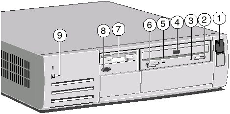 |
| 1 |
Power button |
6 |
CD headphone jack & volume control |
| 2 |
CD Eject button |
7 |
Diskette drive |
| 3 |
CD emergency eject hole |
8 |
Infra-red sensor (optional) |
| 4 |
CD-ROM disc drawer (platter) |
9 |
Hard disk activity indicator |
| 5 |
CD activity indicator |
|
|
 
Rear View
Mini-tower
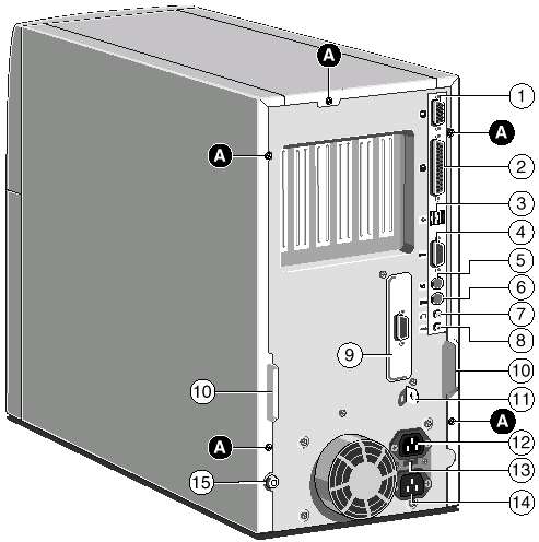 |
| 1 |
Monitor port |
9 |
Serial port 2 (optional) |
| 2 |
Parallel (printer) port |
10 |
Handles to assist side panel removal |
| 3 |
Dual USB port |
11 |
Security loop for cable or padlock |
| 4 |
Serial (modem) port 1 |
12 |
AC power outlet for monitor |
| 5 |
Mouse port |
13 |
Voltage selection switch |
| 6 |
Keyboard port |
14 |
AC power inlet from AC supply |
| 7 |
Audio output socket |
15 |
Caselock |
| 8 |
Audio input socket |
A |
Side panel fixing screws |
Desktop
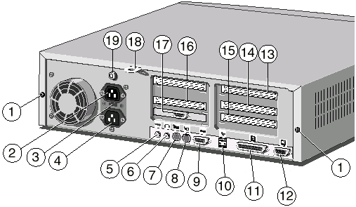 |
1 |
Casing screws for the top cover |
11 |
Parallel (printer) port |
2 |
AC power outlet for monitor |
12 |
Monitor port |
3 |
Voltage selection switch |
13 |
PCI slot (full-length) |
4 |
AC power inlet from AC supply |
14 |
ISA slot (full-length) |
5 |
Audio input socket |
15 |
ISA slot (half-length, half-height) |
| 6 |
Audio output socket |
16 |
PCI slots (two half-length) |
| 7 |
Keyboard port |
17 |
Serial port 2 (optional) |
| 8 |
Mouse port |
18 |
Security loop for cable or padlock |
| 9 |
Serial (modem) port 1 |
19 |
Caselock |
| 10 |
Dual USB port |
|
|
 
Motherboard
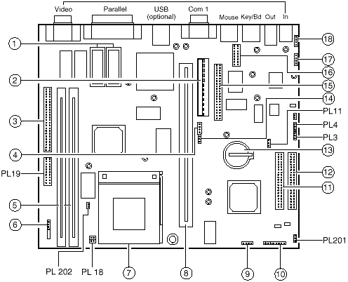 |
| 1 |
Video memory sockets |
11 |
Secondary E-IDE connector |
| 2 |
Motherboard power connector |
12 |
Primary E-IDE connector |
| 3 |
VESA/AMC feature connector |
13 |
CMOS battery |
| 4 |
PSU logic connector |
14 |
"Wake on LAN" connector |
| 5 |
DIMM sockets |
15 |
1.44MB diskette drive connector |
| 6 |
Processor fan-sink connector |
16 |
Second serial port connector |
| 7 |
Processor ZIF socket |
17 |
Modem audio connector |
| 8 |
Riser board connector |
18 |
CD audio connector |
| 9 |
Internal speaker connector |
|
|
| 10 |
Front panel connector
Pins 1-2 POWER button
Pins 3-4 HDD indicator light
Pins 5-6 Unused
Pins 7-8 Power Mode light |
|
|
 
Memory
You can give your PC more memory by adding or replacing memory modules
called "DIMMs". The motherboard’s two DIMM sockets accept DIMMs of up to
128 Mbytes in any combination (giving a maximum memory capacity of 256 Mbytes).
Important
The DIMMs you use must have the following specification: SPD, gold contacts, 3.3V, 64-bit,
unbuffered, either SDRAM-type with a CAS latency of 2 at 66 MHz or else EDO-type with 60
ns timing. If you use any other type of DIMM you risk damaging the motherboard.
 
Add-Ins
| SDRAM memory expansion |
|
| 16MB 64-bit DIMM Module |
XB61385 |
| 32MB 64-bit DIMM Module |
XB61386 |
| 64MB 64-bit DIMM Module |
XB61387 |
| 128MB 64-bit DIMM Module |
XB61388 |
| Video memory expansion |
|
| 1MB to 2MB EDO DRAM upgrade |
XB57374 |
| Graphics cards for PCI motherboards |
|
| Matrox MGA Millenium PCI graphics card add-in with 4MB WRAM |
XB57212 |
| Hard Drive Options |
|
| 2.1GB IDE Stratus
hard disk drive add-in |
SU61670 |
| 3.2GB IDE Stratus
hard disk drive add-in |
SU61671 |
| IDE HDD fixing kit |
SU56129 |
| CD-ROM Drives |
|
| IDE CDU-511 Sony x16
Speed PCAV CD-ROM Drive |
XB61060 |
| IDE Sony CD-ROM Drive Fixing Kit for LS500 |
SU56017 |
| IDE Sony CD-ROM Drive Fixing Kit for LS600 |
SU60353 |
| SCSI card options |
|
| Adaptec 1510B SCSI card add-in (No HDD Support) |
SA50160 |
| Adaptec 2940 PCI SCSI Card add-in |
UD55556 |
| SCSI Fixing Kit for AHA1510 |
SU56213 |
| SCSI Fixing Kit for AHA2940 |
SU56214 |
| Connectivity options |
|
| Intel Pro 100B PCI Ethernet Card |
XB61343 |
| 3Com triple-combo Ethernet card (3C509B) |
XB55742 |
| 3Com 10/100 PCI Ethernet (3C905TX) |
XB59527 |
| 56K ISA Modem |
XB62192 |
| Diamond ISDN Modem (64K) |
XB62494 |
| 8 port Micro Hub & 3 x 5M UTP cables |
XB62451 |
| Specialix serial cards |
|
| 32-port ISA SI/XIO serial card |
XB54693 |
| 4 port terminal adaptor |
XB43319 |
| 8 port terminal adaptor |
XB43320 |
| 8 port modular terminal adapter |
XB54611 |
| 8 port modular terminal adaptor (7 RS232, 1 Parallel) |
XB54612 |
| Audio Options |
|
| Apricot Deepsound Subwoofer |
XB58090 |
| 20W Powered external speakers |
XB55607 |
| Wavetable upgrade for on-board audio |
XB57690 |
| UPS (FT600) |
|
| APC 420v/s smart ups |
XB59898 |
 
Jumper Settings
There are only a few jumpers on the motherboard that you may need to
alter. All others are set at the factory and should not be changed.
On the motherboard, pin 1 of each jumper block is indicated by a small
triangular marking.
Processor voltage and bus speed (PL19, PL18)
Caution
Do not change these jumpers unless you have upgraded the processor. If they are set
incorrectly the processor and other vital motherboard components could be destroyed.
The BF0 and BF1 jumpers on jumper block PL19 may be fitted in the High
("1") or Low ("0") position; the FS, PW2, PW1 and PW0 jumpers may
simply be either fitted across both pins ("In") or not ("Out").

For Pentium processors only, two jumpers must also be fitted on PL18.
These jumpers must not be fitted for Pentium/MMX processors.
| Processor |
Speed |
Jumper block PL19 |
| |
|
BF1 |
BF0 |
FS |
PW2 |
PW1 |
PW0 |
| Pentium |
90 MHz |
High |
High |
In |
In |
In |
In |
| Pentium |
100 MHz |
High |
High |
Out |
In |
In |
In |
| Pentium |
120 MHz |
High |
Low |
In |
In |
In |
In |
| Pentium |
133 MHz |
High |
Low |
Out |
In |
In |
In |
| Pentium |
150 MHz |
Low |
Low |
In |
In |
In |
In |
| Pentium |
166 MHz |
Low |
Low |
Out |
In |
In |
In |
| Pentium |
200 MHz |
Low |
High |
Out |
In |
In |
In |
| Pentium/MMX |
166 MHz |
Low |
Low |
Out |
Out |
Out |
Out |
| Pentium/MMX |
200 MHz |
Low |
High |
Out |
Out |
Out |
Out |
| Pentium/MMX |
233 MHz |
High |
High |
Out |
Out |
Out |
Out |
On-board video disabling (PL19)
If you install a video adapter expansion card, the computer should
automatically detect this and disable the on-board video adapter. If for some reason this
does not happen, and you experience problems with a newly-fitted card, you can manually
disable the on-board video adapter by removing the VGA jumper from jumper block PL19.
Audio disabling (PL19)
The on-board audio system can be disabled by removing the AUD jumper
from jumper block PL19. Disabling the audio system frees the interrupt and DMA channel
used by that system (normally IRQ5 and DMA1).
BIOS upgrade and recovery (PL11, PL4, PL3)
These jumpers should not normally be changed except by a service
engineer or at the direction of a service engineer.
CMOS is cleared by moving the PL11 jumper to the 2-3 position for a few moments while the
system is turned off, then returning it to the normal 1-2 position.
If an error occurs during reprogramming of the BIOS to the extent that the BIOS becomes
corrupt, the PL4 jumper can be moved to the 2-3 (RCVR) position to switch to a recovery
BIOS. A recovery system diskette will be required when the system is restarted.
You must ensure that BIOS reprogramming is enabled if you want to use the optional Apricot
LS Security Card (LOC Technology).
Clearing CMOS PL11
CMOS battery connected (default)1-2
CMOS battery disconnected 2-3
BIOS image selection PL4
Boot using normal BIOS (default) 1-2 (NORM)
Boot using recovery BIOS 2-3 (RCVR)
BIOS reprogramming PL3
Enabled (default) 1-2 (PROG)
Disabled 2-3 (DIS)
Power Mode light colour (PL201)
Normally, the Power Mode light is [red] when the system is in Off mode.
If you move the jumper on block PL201 to pins 2-3 (OFF) the light is extinguished in Off
mode.
 
CMOS
Replacing the configuration battery
The computer keeps a record of its current hardware configuration in a CMOS memory chip
which is sustained by a small battery. This battery has a life of up to 5 years. If you
find that you have to reconfigure the computer every time you turn it on, the battery is
probably failing and needs to be replaced.
The battery is a 3 volt lithium type (CR2032 or equivalent) typically used in calculators
and other small, battery-powered electronic items.
To replace the battery
1. Turn off the computer and unplug all power cords.
2. Take suitable anti-static precautions and remove the system unit cover. For more
information see the section on "Anti-static precautions" in the Safety &
Regulatory Notices at the start of this manual.
3. Remove any expansion cards that impede access to the battery holder.
4. Using a non-conductive implement, release the latch that holds the battery in place.
The battery will pop up allowing you to lift it out of the holder.
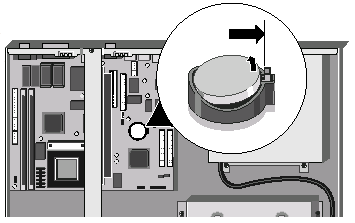
Warning
You must not use a metal or other conductive implement to remove the battery. If a
short-circuit is accidentally made between the battery’s positive and negative
terminals, the battery may explode.
5. Check that the replacement battery looks the same as the battery you
have removed.
6. Taking care not to touch the top or bottom surface of the battery, pick up the
replacement with the positive (+) terminal upwards. Press the battery into the holder
using a non-conductive implement.
7. Replace any expansion cards you removed earlier and refit the system unit cover.
8. Dispose of the discharged battery in accordance with the battery manufacturer’s
instructions.
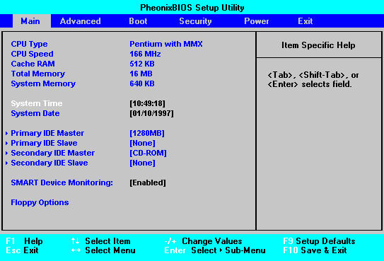
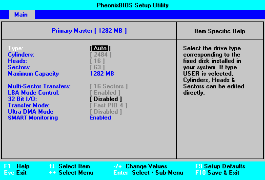
The next time you turn on the computer you will have to run the BIOS Setup utility to
reset the hardware configuration.
Setup Screens

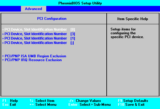
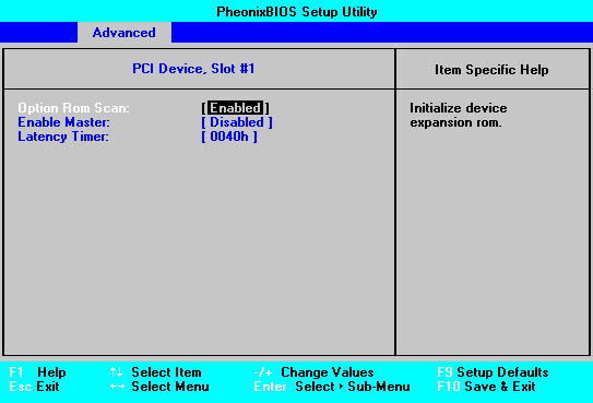
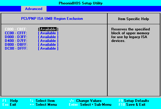
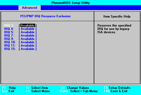
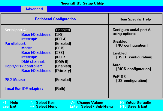
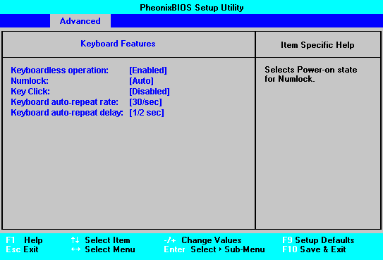


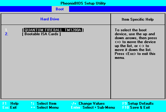
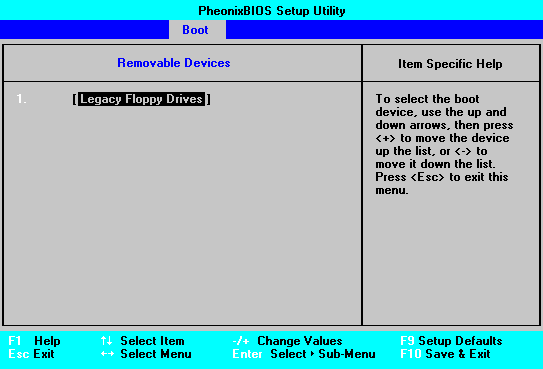
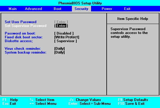
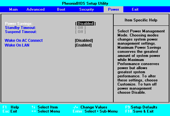
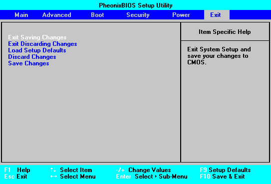
 
System Resources
| Components |
Interrupts (IRQs) |
| |
0 |
1 |
2 |
3 |
4 |
5 |
6 |
7 |
8 |
9 |
10 |
11 |
12 |
13 |
14 |
15 |
| System timer |
|
|
|
|
|
|
|
|
|
|
|
|
|
|
|
|
| Keyboard controller |
|
|
|
|
|
|
|
|
|
|
|
|
|
|
|
|
| PIC daisy chain |
|
|
|
|
|
|
|
|
|
|
|
|
|
|
|
|
| Serial port 2 |
|
|
|
BS |
|
|
|
|
|
|
|
|
|
|
|
|
| Serial port 1 |
|
|
|
|
BS |
|
|
|
|
|
|
|
|
|
|
|
| Audio |
|
|
|
|
|
J |
|
|
|
|
|
|
|
|
|
|
| Diskette controller |
|
|
|
|
|
|
BS |
|
|
|
|
|
|
|
|
|
| Parallel port (usually sharable) |
|
|
|
|
|
|
|
BS |
|
|
|
|
|
|
|
|
| Real time clock |
|
|
|
|
|
|
|
|
|
|
|
|
|
|
|
|
| On-board video |
|
|
|
|
|
|
|
|
|
J |
|
|
|
|
|
|
| USB |
|
|
|
|
|
|
|
|
|
|
BS |
|
|
|
|
|
| Mouse |
|
|
|
|
|
|
|
|
|
|
|
|
|
|
|
|
| Co-processor |
|
|
|
|
|
|
|
|
|
|
|
|
|
|
|
|
| Primary E-IDE |
|
|
|
|
|
|
|
|
|
|
|
|
|
|
|
|
| Secondary E-IDE |
|
|
|
|
|
|
|
|
|
|
|
|
|
|
|
BS |
| Components |
DMA channels |
| |
0 |
1 |
2 |
3 |
4 |
5 |
6 |
7 |
| Audio |
|
J |
|
|
|
|
|
|
| Diskette controller |
|
|
BS |
|
|
|
|
|
| Parallel port (in ECP mode) |
|
|
|
BS |
|
|
|
|
| DMAC daisy chain |
|
|
|
|
|
|
|
|
| BS = Can be disabled by BIOS Setup |
J = Can be disabled by moving a jumper |
|
Fixed assignment |
|
Usual assignment |
|
PnP alternative |
 
POST Beep Codes
Code |
Beeps |
Test which failed |
16 |
1-2-2-3 |
BIOS ROM checksum |
20 |
1-3-1-1 |
DRAM refresh. |
22 |
1-3-1-3 |
8742 keyboard controller |
2C xxxx |
1-3-4-1 |
RAM failure on address line xxxx. |
2E xxxx |
1-3-4-3 |
RAM failure on data bits xxxx of low byte of memory bus. |
30 xxxx |
1-4-1-1 |
RAM failure on data bits xxxx of high byte of memory bus. |
46 |
2-1-2-3 |
Check ROM copyright notice |
58 |
2-2-3-1 |
Test for unexpected interrupts |
98 |
1-2 |
Video configuration failure, or option ROM checksum
failure. (One long, two short beeps.) |
 

|


