FT4200 Cooling Fans (Rel 1.12.1)Warning
Read completely the instructions detailed in Preliminary
Service Information.
Hard Disk Drive Cooling Fan Assembly
You can remove and fit the hard disk drive cooling fan assembly without
disturbing the adjacent disk drive module.
Removing
1. Unplug the middle and bottom fan connectors and their associated
thermistor connectors from the SMC board as shown:
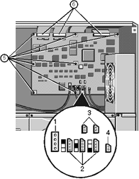 |
| 1 |
Middle & Bottom Fan Connectors |
| 2 |
Associated Thermistor Connectors |
|
2. Push the power and thermistor cables down through the cut-out in the
corner of the metal work behind the top fan assembly.
3. Remove two screws which fasten the fan assembly to the chassis:
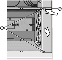 |
| 1 |
Securing Screws |
| 2 |
Finger Grip |
|
4. Use the finger grip to slide the assembly towards you.
Fitting
1. Slide the assembly into position, remembering to feed the guide tabs
into the positioning slots as shown in the following illustration:
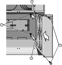 |
| 1 |
Positioning Slots |
| 2 |
Guide Tabs |
| 3 |
Securing Screws |
|
2. At the same time, feed the fan cables through the cut-out in the
corner of the metalwork above the assembly. These cables will need to be plugged into
their respective sockets on the SMC board.
3. Fasten the assembly to the chassis with the two screws.
4. Plug the bottom and middle fan connectors, together with their
associated thermistor connectors, in to the SMC board as indicated in the following
diagram:
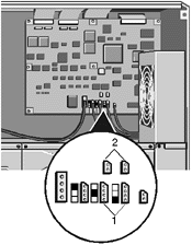 |
| 1 |
Fan Connectors |
| 2 |
Thermistor Connectors |
|
5. Check that all fan and thermistor connections are correctly
orientated before switching on and that all side panels are securely fitted.
The SMC board is marked to show which fans plug in to which socket:
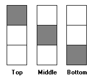
Motherboard Cooling Fan Assembly
Removing
1. Remove five screws on the side of the fan assembly.
2. Remove any support struts fitted across the motherboard.
3. Remove four more screws which fasten the assembly to the centre spine
of the server, as shown:
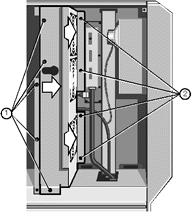 |
| 1 |
Side Securing Screws |
| 2 |
Centre Spine Securing Screws |
|
4. Slide the assembly to the right and then towards you to disengage it.
5. Before removing the assembly entirely, unplug the ribbon cable from
the connector on the small power distribution panel between the bottom and middle fans:
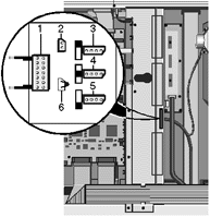 |
| 1 |
Ribbon cable connector |
| 2 |
Side panel lock connector |
| 3,4,5 |
Fan power connectors |
| 6 |
Temperature sensor |
|
Fitting
1. Fit the fan assembly into the interior of the server enough to
connect the ribbon cable to the small power distribution board between the middle and
bottom fans. Ensure the clips are latched onto the connector body.
2. Slide the assembly to the left into place and fasten it to the
chassis by means of four screws at the centre spine and five screws at the side.
3. Replace any card support struts across the motherboard.
Removing fan from assembly
These following instructions apply to all the fans in the server
including any described in other chapters.
Remove the four screws which hold the handguard onto the fan assembly
housing. This not only releases the handguard, but also the fan itself.
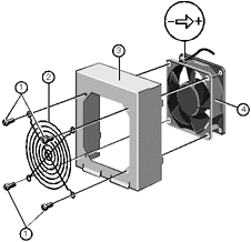 |
| 1 |
Securing Screws |
| 2 |
Handguard |
| 3 |
Fan Assembly Housing |
| 4 |
Fan |
|
Fitting
Caution
Before attempting to fit the fan onto the fan assembly housing, be sure
to place the fan into the assembly so that the air flow through it is from the front of
the server to the rear (see the arrow next to the electrical polarity marking on one
corner of the fan). If any fan is turned the wrong way around, it will seriously reduce
the overall cooling effectiveness and increase the risk of overheating.
1. With the housing upright, align one corner of the handguard with a
screw hole and insert a screw just a few turns.
2. While holding the handguard and screw in place, align the fan to the
other holes and insert a second screw.
In a similar way, align and fit the remaining screws. Tighten when all
are in place. Do not overtighten or this may damage the fan housing.
 

|


