FT4200 Front Panel and Drives (Rel 1.12.1)Warning
Read completely the instructions detailed in Preliminary
Service Information.
Front Bezel
Removing
1. Ensure that the removable media drive bay door is closed and locked.
2. On each side of the server, remove the protective metal plates which
cover the removable media drives and the electronics chamber.
3. Remove any hard disk drive module close to the front of the machine.
For detailed information see previous chapter.
4. Remove eight screws, four on each side of the machine, and slide the
bezel away from the chassis as shown in the following diagram:
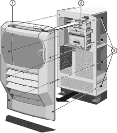 |
| 1 |
Front Bezel |
3 |
Securing Screws (x 8) |
| 2 |
Front Panel System Controller Connector |
|
|
|
5. The front panel is attached to the bezel and comes away from the
chassis at the same time. Since there is a ribbon cable attached to the front panel,
remove the bezel with care.
6. Reach behind the bezel and disconnect the ribbon cable from the front
panel.
Fitting
1. Ensure that any hard disk drive module close to the front of the
machine is removed.
2. Plug the ribbon cable into the connector on the front panel.
Fit the bezel onto the chassis and connect the eight screws, four on
each side of the server, as shown in the following diagram:
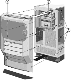 |
| 1 |
Front Bezel |
3 |
Securing Screws (x 8) |
| 2 |
Front Panel System Controller Connector |
|
|
|
Front Panel
Removing
With the front bezel removed and the ribbon cable disconnected from the
front panel, remove the circlip from the top hinge of the removable media drive bay door
(which should be closed and locked).
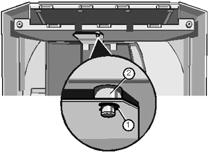 |
| 1 |
Circlip |
2 |
Top Hinge of Drive Bay Door |
|
Gently press down on the metal plate to detach it from the hinge as
shown:
Now remove the two screws as shown:
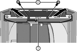 |
| 1 |
Front Panel Supporting Metalwork |
2 |
Securing Screws |
|
4. Slide the supporting metalwork out of the bezel.
Remove the eight screws which fasten the front panel onto the metalwork:
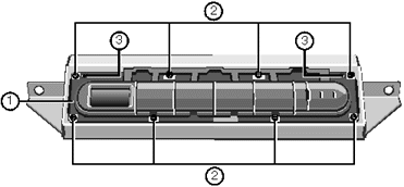 |
| 1 |
Front Panel |
3 |
Metal Protrusion Holes |
| 2 |
Securing Screws |
|
|
|
6. Remove the front panel.
Fitting
Attach the front panel to the supporting metalwork by means of the eight
screws as shown:
 |
| 1 |
Front Panel |
3 |
Metal Protrusion Holes |
| 2 |
Securing Screws |
|
|
|
Note
Be sure to fit the two securing holes, marked ‘3’,
over the small metal protrusions in the metalwork.
Insert the front panel framework into the bezel as shown:
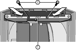 |
| 1 |
Front Panel Supporting Metalwork |
2 |
Securing Screws |
|
3. Fasten the framework onto the bezel using the two screws.
4. Attach the top hinge of the removable media drive bay door to the
front panel supporting metal work you just fitted.
Fit the circlip into the hinge as shown in the following illustration:
1. Circlip 2. Top Hinge of Drive Bay Door
Removable Media Drives
To gain access to the removable media drives and the System Management
Controller (SMC) you must first remove the protective metal plate which covers this area.
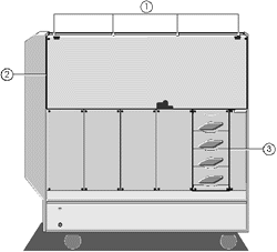 |
| 1 |
Securing Screws |
3 |
Hard Disk Subsystem |
| 2 |
Protective Metal Plate |
|
|
|
1. Remove the securing screws.
2. Use the finger holes near the top left and right-hand corners to lift
the plate away from the server.
Removing
Each drive is attached to a drive tray, which is in turn secured to the
drive cage. To remove a tray from the cage:
1. Unplug the data and power cables from the rear of the drive. Unplug
the other end of the power cable from its socket on the centre spine.
Remove the two drive tray securing screws from the side of the cage. The
following diagram shows the screws for three of the drives:
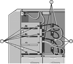 |
| 1 |
Drive Tray Securing Screws |
3 |
Drive Data Cables |
| 2 |
Drive Power Cables |
|
|
|
3. Slide the tray carefully toward the rear of the cage until it is free
from the metalwork.
Turn the tray over and remove four screws from the underside.
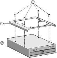 |
| 1 |
Drive Tray |
3 |
Securing Screws |
| 2 |
Drive Assembly |
|
|
|
5. Lift the tray away from the drive.
Fitting
Your server is equipped with a tray and a blanking plate for each empty
drive bay.
1. Remove the blanking plate, if necessary, from the drive tray. The
plate is attached via two screws on the underside of the tray.
2. Fasten the drive onto a drive tray using the four securing screws as
shown above. The tray allows for a small amount of adjustment. Align carefully, if the
drive is too far forward it may prevent the front panel door from closing.
3. Turn the drive upright, slide it into the drive cage and secure it to
the cage using the two screws.
4. Connect the power cable to the back of the drive and the other end to
the socket on the centre spine.
5. If you are fitting a SCSI drive, you will need to connect it to the
bus cable which is attached to any other SCSI removable media drives that are present.
Note
When fitting SCSI devices, the unit ID must be set so as not to
conflict with any other SCSI device already in the system. It is advisable to keep a
secure written record of all devices, IDs and their function/position.
 

|


