FT4200 Power Distribution Panels and Loudspeaker (Rel 1.12.1)There are two
separate power distribution panels, one for hard disk drives and one for Removable Media
drives.
Warning
Read completely the instructions detailed in Preliminary
Service Information.
Hard Disk Drive Power Distribution Panel
Removing
1. Remove the motherboard cooling fan assembly as detailed in chapter 8.
This uncovers three bus bars which are attached to the power
distribution panel, through a cut-out in the centre spine, and to the power supply, as
shown in the following illustration:
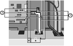 |
| 1 |
Bus Bars |
2 |
Connections to Hard Disk Power Distribution Panel |
|
3. Detach the three bus bars from the distribution panel.
4. In the disk chamber, remove all hard disk drives and drive modules.
Also, remove any blanking plates that cover empty disk chamber space.
5. Remove 11 screws as shown in the following diagram and lift out the
panel.
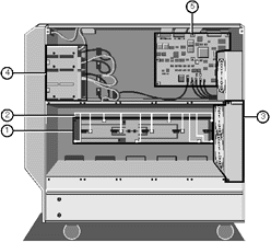 |
| 1 |
Power Distribution Panel |
4 |
Removable Media Drives |
| 2 |
Securing Screws |
5 |
SMC Board |
| 3 |
HD Cooling Fan Assembly |
|
|
|
Fitting
1. With all hard disk drives, drive modules and the motherboard cooling
fan assembly removed, attach the hard disk distribution board to the centre spine of the
server, in the disk chamber, using the 11 screws as shown above.
2. Refit all the hard disk drive modules and drives.
Caution
It is vital that you remember the exact cable and connector
arrangement of your hard disks, particularly if you are using a RAID (Redundant Array of
Independent Disks) configuration. If you fail to restore the arrangement so that all
cables and plugs are as they were originally, you risk losing all the data on your hard
disks.
3. Reconnect the bus bars in the electronics chamber.
Note
You must use a torque wrench to tighten the bus bar bolts. The torque
wrench setting is 5 Newton metres (Nm).
4. Replace the motherboard cooling fan assembly.
Removable Media Drive Bay Power Distribution Panel
Removing
In the electronics chamber, unplug two power cables as shown in the
following diagram:
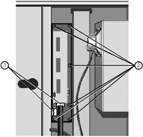 |
| 1 |
Cable Connectors |
2 |
Securing Screws |
|
2. In the disk chamber, unplug the cables which provide power to the
removable media drives.
3. Now remove the six screws which fasten the power distribution board
to the centre spine and remove the board, as shown in the previous diagram.
Fitting
1. Fasten the power distribution panel onto the centre spine of the
server with the six screws as shown above.
2. Connect the two power cables as shown in the previous illustration.
3. In the disk chamber, reconnect the cables which provide power to the
removable media drives.
Loudspeaker
Removing
1. Remove the motherboard cooling fan assembly as previosly detailed.
Unplug the loudspeaker cable from the connector on the motherboard power
distribution panel, as shown:
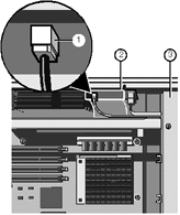 |
| 1 |
Loudspeaker Connector |
3 |
Cooling Fan Assembly |
| 2 |
Power Distribution Panel |
|
|
|
Remove the four screws which fasten the loudspeaker onto the front drive
bay door housing, as shown:
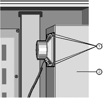 |
| 1 |
Loudspeaker Securing Screws |
2 |
Removable Media Drive Bay |
|
Fitting
1. Use the four screws to attach the loudspeaker to the front drive bay
door housing, as shown above.
2. Plug the cable into the loudspeaker connector on the motherboard
power distribution panel and
3. Refit the motherboard cooling fan assembly.
 

|


