FT4200 System Management Controller Board and Fan (Rel 1.12.1)Warning
Read completely the instructions detailed in Preliminary
Service Information.
Although some of the board is hidden behind the cooling fan assembly,
all of the fixing screws and cable connections are easily accessible.
System management controller (SMC)
Removing
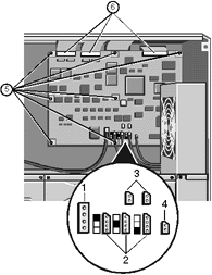
Take careful note of where each connection is from and unplug three
ribbon cable connectors, the power connector, three fan connectors, two thermistor
connectors and one keylock sensor cable connector as shown in the following diagram:
 |
| 1 |
Power Connector |
| 2 |
Fan Connectors |
| 3 |
Thermistor Connectors |
| 4 |
Keylock Sensor Connector |
| 5 |
Securing Screws |
| 6 |
Ribbon Cable Connectors |
|
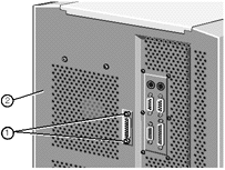
Remove the two screw lock posts on the 25-way SMC serial port connector
which is visible on the server’s back panel:
 |
| 1 |
Screw Lock Posts |
| 2 |
Back panel |
|
3. Remove the seven fastening screws and lift the board out of the
machine.
Fitting
1. Feed the 25-way serial port connector through the opening in the back
panel.
2. Fasten the board to the centre spine using the seven screws as
previously removed
3. Fasten the two screwlock posts into place at both ends of the 25-way
connector on the back panel.
4. Plug the ribbon cables, power cable, fan and associated thermistor
cables and the keylock sensor cable into their respective connectors on the SMC board as
shown in the previous diagram. Ensure the ribbon to the front panel is returned to the top
left connection.
Caution
Ensure the ribbon cables from the front panel and the PSU are in
their correct positions or damage will be caused to the SMC board.
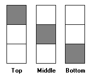
Against each fan connector on the board there is a graphic which
indicates which fan cable should be plugged in:

The middle and bottom fans in this series are located below the SMC
board in the disk subsystem area.
System Controller Cooling Fan Assembly
Removing
1. Unplug the top fan connector on the SMC board (see fan connector
graphic in "System Management Controller Board, Fitting").
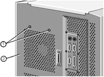
Remove the two securing screws for the fan assembly, found on the back
panel as shown:
 |
| 1 |
Securing Screws |
| 2 |
Back panel |
|
Tilt the top of the assembly slightly towards the interior of the server
(if it hasn’t already) and lift it upwards to free it from the chassis
Fitting
1. Fit the assembly so that the two metal tabs at the bottom are
inserted into corresponding slots. The assembly will then have a natural tilt towards the
interior of the server.
2. On each side of the assembly there is also a smaller tab which fits
into a corresponding slot in the chassis. Squeeze the sides gently until the tabs fit into
the slots.
3. While holding the assembly in place, fasten it with the two screws on
the back panel of the server.
4. Connect the fan cable to the top connector on the controller
board.
Against each fan connector on the board there is a graphic which
indicates which fan cable should be plugged in:

For further information about dismantling the fan sub-assembly, see the
following chapter, which provides detailed instruction on the rest of the internal system
fans.
 

|


