FT4200 Uninterruptible Power Supply Unit & Battery Pack (Rel 1.12.1)Warning
Read completely the instructions detailed in Preliminary
Service Information.
The UPS unit consists of the actual power supply and the accompanying
battery pack. The unit is very robust but is very heavy, approximately 35 Kg including
battery pack.
If you are going to remove the power supply, always do it as a single
unit. Do not remove the battery pack first. The unit is severely out of balance
without the battery pack and could unexpectedly roll over as you remove it.
It is essential that you use the utmost care when removing the UPS in
order to avoid injury to yourself or damage to the unit. Do not attempt to remove or fit
the unit alone. There should always be at least one other person available to help you.
Before you begin, ensure that the server is in a suitable area with
plenty of work space. Then, use the jacking mechanism in the front castors to anchor them
firmly to the floor so that the server cannot roll about.
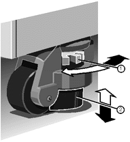 |
| 1 |
Adjustment Wheel |
| 2 |
Jacking Pad |
|
Uninterruptible Power
Supply Unit
Removing
1. It is vitally important to ensure that the system is shut
down, the battery pack circuit breaker switch is in the Off position and the system is
disconnected from the mains electricity supply.
2. If necessary, remove some of the expansion cards to improve access to
the bus bars, which provide power to the motherboard. You may also need to unplug some of
the data cables which are connected to the hard disk drive modules.
Caution
It is vital that you remember the exact cable and connector
arrangement of your hard disks, particularly if you are using a RAID (Redundant Array of
Independent Disks) configuration. If you fail to restore the arrangement so that all
cables and plugs are as they were originally, you risk losing all the data on your hard
disks.
3. Remove the motherboard cooling fan assembly as detailed in chapter 8.
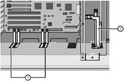
Detach two pairs of motherboard bus bars and remove the set of 3 bus
bars under the cooling fan assembly as shown in the following diagram:
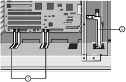 |
| 1 |
Motherboard Bus Bars |
| 2 |
Bus Bars for Hard Disk Power Distribution Panel |
|
5. Make sure that there is enough clearance between the bus bars and
their power supply connections to allow the unit to slide freely.
If there is not enough clearance, you will need to disconnect the other
ends of the busbars and remove them completely. Take a careful note of each busbar and the
position it was removed from.
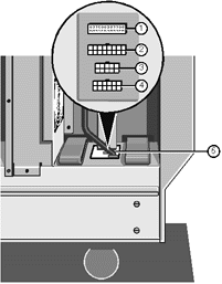
Unplug three cables, one ribbon, one 12-way and one 16-way, from the
power supply as shown:
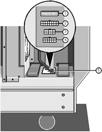 |
| 1 |
System Controller (Ribbon Cable) Connector (12-way) |
| 2 |
Motherboard Auxiliary Power (16-way) |
| 3 |
Not used |
| 4 |
Removable Media Drive Bay |
| 5 |
Cable Connector Group |
|
Loosen four floating fasteners, two on each side of the server, until
they are free of the power supply unit, as indicated in the following diagram:
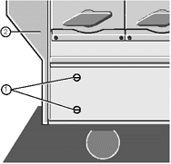 |
| 1 |
Floating Fasteners |
| 2 |
Front Bezel |
|
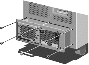
Now remove six screws on the back panel of the server, as shown:
Using the handle on the battery pack, pull the unit carefully
until it is a little less than halfway out (about 30 cm), just before it begins to tip
towards you.
Warning
This Power supply is heavy. It is strongly advised to have a second
person with you to assist before you either fully remove the assembly from the server, or
pick it up to fit it into its position in the server.
10. The second person should assist you, on the opposite side of the
unit, from this point onwards.
Place your hands under the metal casing of the unit as indicated by the
arrows in the following illustration:
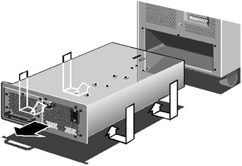
Slide the unit out slowly until it is free from its housing. Now
rest the unit on the floor. Do not drop it.
Fitting
1. With the help of the second person on the opposite side, place your
hands underneath the power supply as indicated by the arrows in the illustration above.
2. Now carefully slide the unit all the way into the chassis.
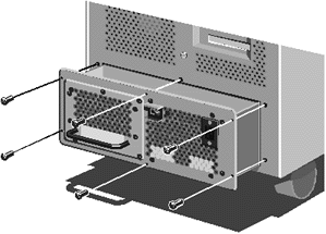
Secure the unit to the chassis with the six screws as shown:
Now tighten the four floating fasteners, two on each side, located
towards the front of the machine:
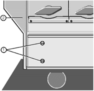 |
| 1 |
Floating Fasteners |
| 2 |
Front Bezel |
|
5. Plug the ribbon, 12-way and 16-way cables into their connectors
on the power supply.
Note that these connectors are keyed and can only be fitted in one
position.
 |
| 1 |
System Controller (Ribbon Cable)Connector (12-way) |
| 2 |
Motherboard Auxiliary Power (16-way) |
| 3 |
Not used |
| 4 |
Removable Media Drive Bay |
| 5 |
Cable Connector Group |
|
6. Attach two pairs of bus bars and fit one set of 3 bus bars as shown
in the following diagram.
As with the cables, it should not be possible to fit these bars
incorrectly.
 |
| 1 |
Motherboard Bus Bars |
| 2 |
Bus Bars for Hard Disk Power Distribution Panel |
|
Caution
The hardware used to hold the busbar connections must be tightened
using a torque wrench set to 5 Newton meters (Nm).
7. Fit the motherboard cooling fan assembly.
8. Refit any expansion cards you may have removed to improve access.
Caution
It is vital that you remember the exact cable and connector
arrangement of your hard disks, particularly if you are using a RAID (Redundant Array of
Independent Disks) configuration. If you fail to restore the arrangement so that all
cables and plugs are as they were originally, you risk losing all the data on your hard
disks.
UPS Battery Pack
The UPS is equipped with a replaceable battery pack. It will provide
electric power for your system for a specific period of time, depending on how many hard
disks or other devices are installed. Use the SMA at any time to find out the exact
battery life remaining (see the SMA User’s Guide for more details).
Do not attempt to remove the power supply if the battery pack has
already been removed, as it will cause a serious imbalance, the battery pack can
however be removed as an individual component.
Important - Warning
The battery pack contains lead acid batteries. In the EEC the
directive 91/157/EEC (plus subsequent amendment 93/86/EEC) designates batteries containing
lead to be handled as a dangerous substance.
Similar regulations will apply in other countries.
The battery pack must only be removed by a qualified electrician
and must not be disposed of in domestic waste.
Removing
Remove the fastening screws as shown in the following diagram:
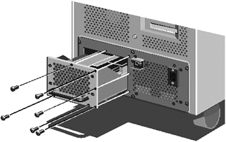
Pull the battery pack handle carefully and slide out slowly until
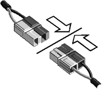
the pack hits a ‘stop’. The following power connector will then be visible:
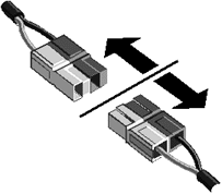
Gently pull the connector apart as indicated.
4. Now with a slight lift, you can remove the battery pack clear. (There
is a further ‘end-stop’ to prevent the battery pack’s rear end falling
out.)
Fitting
1. Make sure that the battery pack power connector is visible and
accessible.
2. Carefully lift the battery pack over the ‘end-stop’ and
slide it far enough into the chassis to reconnect the battery pack power connector.
Push the pack the rest of the way into the chassis, lifting slightly to
pass over the ‘stop’.
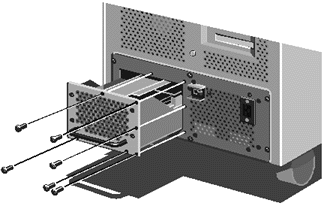
Use the screws as shown in the previous diagram to secure the battery
pack.
 

|


