Shogun Hard Disk Drive Module (Rev 1.8.1)The hard disk
drive module is the removable metal framework which holds up to four hard disk drives. The
Shogun disk subsystem can accommodate up to five of these modules. Removal of a module
will usually only be necessary if the circuit boards on the module backplane fail.
Removing
1. Remove all hard disk drives which may be
fitted to the module in question.
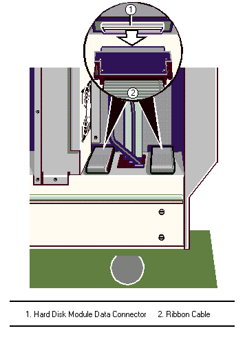
2. In the electronics chamber, unplug the data ribbon cable from the
connector on the back of the module. The connector is visible through an opening in the
centre spine.
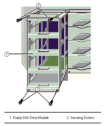
3. Remove the four securing screws, as shown:
4. Slide the module gently out. You will feel the backplane power
connector unplug from the socket on the centre spine of the server.
Fitting
1. Remove the knockout panel (first time only) which covers the drive
module data connector opening in the centre spine of the server.
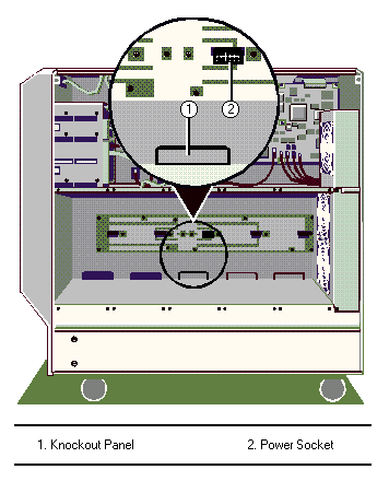
2. Slide the drive module into place, guiding the data connector through
the opening in the centre spine. You will feel the module snap into place as the power
connector on the backplane plugs into the socket on the centre spine.

3. Use the four screws to fasten the module to the subsystem metalwork.
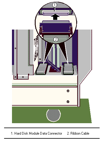
4. In the electronics chamber, plug the appropriate ribbon cable onto the data connector
on the backplane of the drive module:
It has been found that when fitting the fifth module it is easier to
install when the forth module is removed. Install the fifth module and then re-install the
forth module.
Hard Disk Drive Module Backplane
The backplane on a hard disk drive module consists of up to seven small
circuit boards which are fastened with screws to the metal framework and connected to each
other by a flexible ribbon cable.
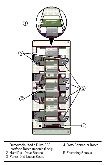
Removing
There are two fastening screws for each board except the removable media
drive SCSI interface board, which has four. To remove the backplane:
1. Remove all disk drives from the module.
2. Remove the fastening screws from all the boards.
3. Push each of the boards, except the data connector board, towards the interior of the
module and manoeuvre it as necessary until it can be freed from the framework.
4. Lift the backplane away.
Fitting
1. Manoeuvre the boards of the backplane through the back openings into
the interior of the framework so that they can be positioned properly.
2. Fasten all the boards to the module framework as shown in the diagram above.
 

|


