
 |
|
 |
|
|||||||||||||||||||||||||||||||||||||||||||||||||||||||||||||||||||||||||||||||||||||||||||||||||||||||||||||||||||||||||||||||||||||||||||||||||||||||||||||||||||||||||||||||||||||||||||||||||||||||||||||||||||||||||||||||||||||||||||||||||||||||||||||||||||||||||||||||||||||||||||||||||||||||||||||||||||||||||||||||||||||||||||||||||||||||||||||||||||||||||||||||||
 |
 |
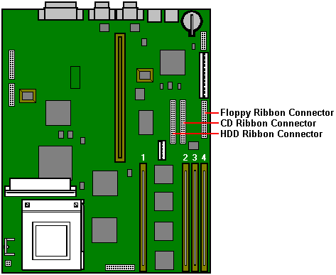
The memory is fitted in four vertical DIMM sockets which must be populated with gold, 3.3V, 72-bit DIMM 80, 70 and 60ns timings are supported, but 60ns results in much tighter memory control and may considerably improve system performance with some software.
View of DIMM

Although the minimum configuration is one DIMM there are considerable performance benefits in fitting more than one DIMM. 2-way or 4-way interleave become available when two, or four DIMMs respectively, are fitted. All 4 must be same speed.
RAM Configuration
Total Memory |
Bank 1 |
Bank 2 |
Bank 3 |
Bank 4 |
4 Mb |
4 Mb |
- |
- |
- |
8 Mb |
4 Mb |
4 Mb |
- |
- |
8 Mb |
8 Mb |
|||
16 Mb |
4 Mb |
4 Mb |
4 Mb |
4 Mb |
16 Mb |
8 Mb |
8 Mb |
||
16 Mb |
16 Mb |
|||
32 Mb |
8 Mb |
8 Mb |
8 Mb |
8 Mb |
32 Mb |
16 Mb |
16 Mb |
||
32 Mb |
32 Mb |
|||
64 Mb |
16 Mb |
16 Mb |
16 Mb |
16 Mb |
64 Mb |
32 Mb |
32 Mb |
||
64 Mb |
64 Mb |
|||
128 Mb |
32 Mb |
32 Mb |
32 Mb |
32 Mb |
128 Mb |
64 Mb |
64 Mb |
||
128 Mb |
128 Mb |
|||
256 Mb |
64 Mb |
64 Mb |
64 Mb |
64 Mb |
256 Mb |
128 Mb |
128 Mb |
||
512 Mb |
128 Mb |
128 Mb |
128 Mb |
128 Mb |
| 3Com triple-combo (thin/thick/UTP) Ethernet card, (3C509B) | XB55742 |
| 3Com 10/100 PCI (3C595TX) | XB54991 |
| MB | Make | Model | Type | Part Number |
| 850 | Quantum | TB 850 AT | IDE | SU54941 |
| 1,200 | Quantum | TM 1280 AT | IDE | SU59082/font> |
| 2,100 | Quantum | TM 2110 AT | IDE | SU59083 |
| 3,200 | Quantum | TM 3200 AT | IDE | SU59084 |
| Tape Drives | ||||
| 400 - 800MB | Conner | CTT800R-F | Floppy | XB56352 |
| 4-16 GB | Conner | CTD8000R-S | DDS II SCSI | SU54778 |
| 1.6-3.2 GB | Conner | CTM3200R-S | SCSI | XB54027 |
| Floppy Drives | ||||
| 2 MB | Mitsubishi | 355F-2450MP | 3.5" | |
| CD-ROM Drives | ||||
| Sony | CDU77E-10 | IDE | SU54763 | |
| Sony | CDU76S-01 | SCSI | SU54768 | |
BIOS Control Links
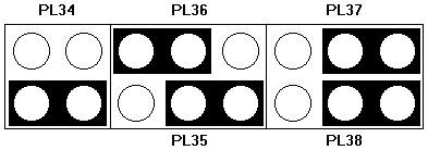
Floppy disk control mode
PL34, default position link pins 3 and 4. To enable 3-mode operation of the drive (Japan
only), link pins 1 to 3 and 2 to 4.
BIOS Recovery
PL35, default position as shown above. If a problem occurs during BIOS upgrade, move to
other pins to recover BIOS from protected area of ROM.
BIOS Re-program
PL36, default position as shown above. To write enable the BIOS for an upgrade, move the
link to other pins.
BIOS Password
PL37, default position as shown above. Locks password into the BIOS. To release, move
llink to other pins.
Clear CMOS
PL38, default position as shown above. To wipe all BIOS settings (extreme caution
advised), move link to other pins.

| BUS clock speed | |
| Multiplier | |
| PL11 and PL12 are reserved for certain video options if an on-board video system is fitted. Any fitted links should not be removed. | |
| Processor settings examples | |

| PL16 Keylock and power on LED | PL1 Main system fan supply |
| PL17 Standby power switch | PL2 Processor fan supply |
| PL18 System in standby LED | |
| PL20 Drive active LEDs | |
| PL21 Speaker | |
| PL22 IRDA | |
| PL23 System hardware reset |
Other Motherboard Connections
| Modems | ||
| V32 data/fax/voice modem. | XB55987 | |
| V34 data/fax/voice modem. | XB57689 | |
| Add-in Cards | ||
| Hauppage TV Card | ||
| Radio Card | ||
| Matrox MGA Millenium PCI, 2MB WRAM (See Note below) | XB57211 | |
| Matrox MGA Millenium PCI, 4MB WRAM (See Note below) | XB57212 | |
| SCSI card add-in (No HD Support) | SA50160 | |
| Adaptec 2940 PCI SCSI card | UD55556 |
| NOTE: | Matrox |
| MGA Impression | |
| MGA Impression Plus | |
| MGA Millennium |
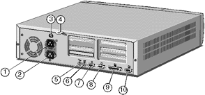
| 1 - AC Power Inlet | 5 - Keyboard Port | 9 - Parallel Port |
| 2 - AC Power Outlet | 6 - Mouse Port | 10 - Video Port |
| 3 - Optional Case Lock | 7 - Serial Port 1 | |
| 4 - System Security Loop | 8 - Serial Port 2 |
To discharge CMOS refer to jumper PL38
When this appears in the top right of the screen press the F1 on the keyboard and in a few seconds you will be presented with the BIOS setup screen (see below)
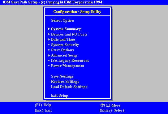
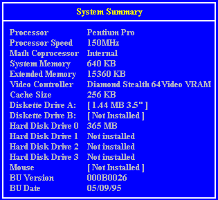


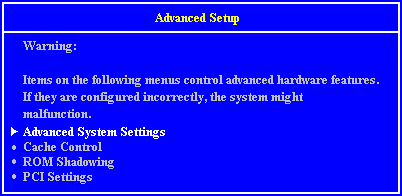

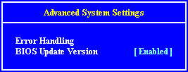
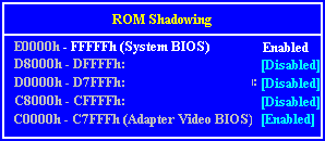
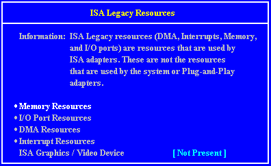
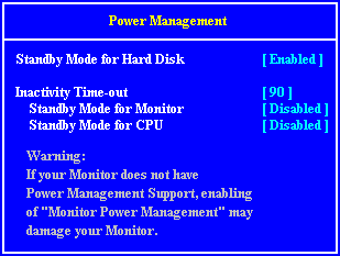
Interrupts, Memory & I/O Ports
Interrupts (IRQ)
Interrupts |
Default Function |
Available ? |
IRQ 0 |
System timer |
No |
IRQ 1 |
Keyboard |
No |
IRQ 2 |
PIC daisy chain |
No |
IRQ 3 |
Serial port 2 |
Can be freed by disabling port |
IRQ 4 |
Serial port 1 |
Can be freed by disabling port |
IRQ 5 |
Not used |
Yes |
IRQ 6 |
Diskette controller |
Can be freed by disabling port |
IRQ 7 |
Parallel port |
Can be freed by disabling port |
IRQ 8 |
Real time clock |
No |
IRQ 9 |
Not used |
Yes |
IRQ 10 |
Not used |
Yes |
IRQ 11 |
Not used |
Yes |
IRQ 12 |
Mouse |
No |
IRQ 13 |
Co processor |
No |
IRQ 14 |
Primary ATA/IDE interface |
Can be freed by disabling port |
IRQ 15 |
Secondary ATA/IDE interface |
Can be freed by disabling port |
I/O Ports
I/O ports (Hex) |
Used by |
1F0 - 1F7 |
Hard Disk Drive Controller |
200 - 207 |
Game I/O |
278 - 27F |
Parallel Port 2 |
2B0 - 2DF |
Alternate VGA |
2F8 - 2FF |
Serial Port 2 |
378 - 37F |
Parallel Port 1 |
3B0 - 3BF |
Monochrome Display and Printer Adapter |
3B4, 3B5, 3BA |
Video Subsystem |
3C0 - 3C5 |
VGA |
3C6 - 3C9 |
Video DAC |
3CA - 3DF |
VGA |
3F0 - 3F7 |
Diskette Drive Controller |
3F8 - 3FF |
Serial Port 1 |
All addresses below 100h are used by the system board for various fixed system components and chipset controller settings.Any other ports not listed are available for expansion cards.
Direct memory access (DMA) channel
DMA |
Default Function |
Available ? |
DMA 0 |
Yes | |
DMA 1 |
Alternate ECP printer port |
Optionally |
DMA 2 |
Diskette Controller |
No |
DMA 3 |
Enhanced Capabilities Port |
Optionally |
DMA 4 |
DMAC daisy chain |
No |
DMA 5 |
Yes | |
DMA 6 |
Yes | |
DMA 7 |
Yes |
![]()