XEN-PC (A1)
Motherboard (Rev 1.3.11)
 
RAM Configuration
On-Board |
SIMM 1 |
SIMM 2 |
Total |
4 MB |
- |
- |
4 MB |
4 MB |
- |
4MB |
8 MB |
4 MB |
- |
8 MB |
12 MB |
4 MB |
- |
16 MB |
20 MB |
4 MB |
4 MB |
- |
8 MB |
4 MB |
4 MB |
4 MB |
12 MB |
4 MB |
4 MB |
8 MB |
16 MB |
4 MB |
4 MB |
16 MB |
24 MB |
4 MB |
16 MB |
- |
20 MB |
4 MB |
16 MB |
4 MB |
24 MB |
4 MB |
16 MB |
8 MB |
28 MB |
4 MB |
16 MB |
16 MB |
36 MB |
 
Ethernet Options
| IBM Token Ring card |
XB42148 |
| IBM Token Ring card Remote Boot ROM |
SN47602 |
| 3Com Ethernet card, thin/thick (3C503) |
XB50902 |
| 3Com Ethernet card, UTP/Thick (3C503B-TP) |
XB50901 |
| 3Com triple-combo (thin/thick/UTP) Ethernet card, (3C509) |
XB51623 |
| 3Com AUI to UTP Transceiver (3C583) |
XB50900 |
 
Disk Drives
 
Jumper Settings
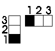 Jumper
numbering looking from the front of the machine. Jumper
numbering looking from the front of the machine.
BIOS
| JP1 |
Open |
Original BIOS |
| |
Closed |
OEM BIOS |
Security
| JP2 |
1 - 2 |
Enable Security |
| |
2 - 3 |
Disable Security |
ROM Type
| JP4 |
1 - 2 |
Flash ROM, 28Fxxx |
| |
2 - 3 |
EPROM, 27xxx |
Floppy Type
| JP5 |
1 - 2 |
Normal Floppy |
| |
2 - 3 |
3 Mode Floppy |
I/O Address for Local IDE
| JP6 |
1 - 2 |
AD12, I/O 03Xh |
| |
2 - 3 |
AD12, I/O 0BXh |
Local IDE
| JP16 |
Open |
Enable AD12 (Local IDE) |
| |
Closed |
Disable AD12 |
Cache Size
Cache |
JP24 |
JP25 |
JP26 |
64 K |
Open |
Open |
2 - 3 |
128 K |
Open |
Closed |
1 - 2 |
256 K |
Closed |
Closed |
2 - 3 |
On-Board Video
| JP14 |
Open |
Disable On-Board VGA |
| |
Closed |
Enable On-Board VGA |
On-Board Memory
| JP28 |
1 - 2 |
Enable On-Board Memory |
| |
2 - 3 |
Disable On-Board Memory or On-Board Memory None |
CPU Type
CPU |
JP11 |
JP12 |
JP13 |
JP15 |
JP18 |
JP20 |
JP27 |
486 |
1 - 2 |
1 - 2 |
1 - 2 |
1 - 2 |
2 - 3 |
2 - 3 |
Open |
P24T |
1 - 2 |
2 - 3 |
1 - 2 |
2 - 3 |
1 - 2 |
2 - 3 |
Open |
M6 |
2 - 3 |
1 - 2 |
2 - 3 |
2 - 3 |
2 - 3 |
1 - 2 |
Open |
M7 |
2 - 3 |
1 - 2 |
1 - 2 |
2 - 3 |
2 - 3 |
2 - 3 |
Open |
M6 & C6 |
2 - 3 |
1 - 2 |
2 - 3 |
2 - 3 |
2 - 3 |
1 - 2 |
Closed |
CPU Speed
Speed |
JP7 |
JP8 |
JP9 |
JP10 |
JP17 |
25 (DX2-50) |
2 - 3 |
2 - 3 |
1 - 2 |
2 - 3 |
2 - 3 |
33 (DX2-66) |
1 - 2 |
2 - 3 |
1 - 2 |
2 - 3 |
2 - 3 |
40 |
1 - 2 |
1 - 2 |
2 - 3 |
1 - 2 |
1 - 2 |
50 |
2 - 3 |
2 - 3 |
1 - 2 |
1 - 2 |
1 - 2 |
Key
| JP22 |
Open |
Lock Key |
| |
Closed |
Unlock Key |
 
Additional Options
AdLOC Security card XB001
Other Memory Expansion
1Mb to 2Mb Video RAM upgrade SH52450
0Kb to 256Kb Cache RAM upgrade SH52451
128Kb to 256Kb Cache RAM upgrade SH53372
Modems
TripleX modem - internal modem card V21, V22 & V23 XB8762
 
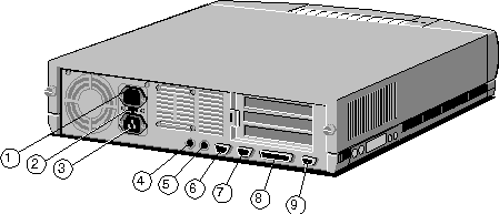
Rear Panel
 
CMOS
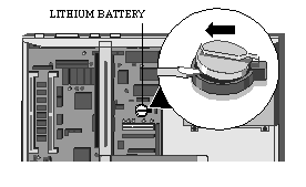
To discharge CMOS remove the Lithium battery as shown below.
LITHIUM BATTERY
This battery has a life of 3 years, and is user replaceable when discharged. The XEN-PC
uses a 3V lithium battery, used in calculators and other small, battery powered electronic
items. The battery used in the XEN-PC is a CR2032 or equivalent.
Invoking SETUP
The SETUP utility can be invoked at any time using the CTRL+ALT+ESC
key combination.
 
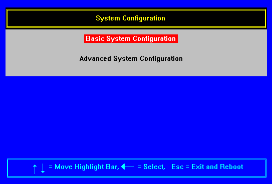
Initial Menu
When you invoke SETUP the initial menu contains two choices as shown
below.
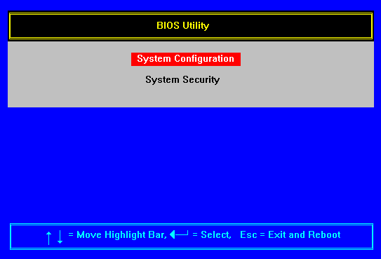
Use the Up and Down arrow keys to move the highlight bar to the item of
your choice, and the return key to select that item.
 
System Configuration
 
Basic System Configuration Page 1 of 2
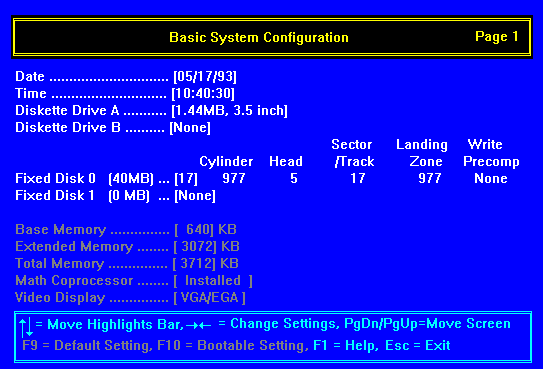
Date
The SETUP utility shows the system shows the system date in month, day, year format. Use
the up and down arrow keys to select the parameter you want to change, then use the left
and right arrow keys to scroll through the possible values until you reach the correct
one.
Once the correct date is set you should not need to set it again.
Time
The SETUP utility shows the system date in hour, minute, second format. Use the up and
down arrow keys to select the parameter you want to change, then use the left and right
arrow keys to scroll through the possible values until you reach the correct one.
Once the correct time is set you should not need to set it again, except
when the clocks change at the beginning and end of summer time.
Diskette Drives
Each of the two diskette drives have five possible settings.
These are:
not present
360K, 5.25 inch
1.2MB, 5.25 inch
720KB, 3.5 inch
1.44MB, 3.5 inch
Use the up and down arrow keys to select the parameter you want to
change, then use the left and right arrow keys to scroll through the possible values until
you reach the correct one.
In XEN-PC diskette drive A is always a 1.44MB, 3.5 inch drive.
In XEN-PC diskette drive B is normally not present, if a second drive is
fitted it will usually be a 1.2MB, 5.25 inch drive.
Fixed Disk Drives
It is important that you select the correct drive type for your hard disk drive(s). The
SETUP utility provides a number of methods of entering drive type information.
The simplest method for a single hard disk is to select drive type 255
then press F8. SETUP then interrogates the drive and automatically sets the drive type
information.
Warning
If pressing F8 results in a drive type with more than 1024 cylinders you must change the
drive type to 80.
Selecting the wrong drive type may result in losing capacity, or, if the
drive is already formatted, data. It is recommended that the first time you power up our
XEN-PC you invoke SETUP and make a note of the drive type parameters. This will ensure
that you can always reconfigure the drive type correctly.
Alternatively if you know the drive type use the left and right arrow
keys to scroll through the list of drive types until you find the correct one.
If you wish, you can manually enter parameters by selecting drive type
255 then pressing return. Use the return key, or the left and right arrow keys, to move
along the line of parameters entering the numbers as you go. When you have finished press
Esc.
Warning
If pressing F8 results in a drive type with more than 1024 cylinders you must change the
drive type to 80.
Selecting the wrong drive type may result in losing capacity, or, if the
drive is already formatted, data. It is recommended that the first time you power up our
XEN-PC you invoke SETUP and make a note of the drive type parameters. This will ensure
that you can always reconfigure the drive type correctly.
For dual drive systems unless both drives are the same you must know the
drive type of at least one drive. Select the correct drive type for one drive, then use
any of the methods given earlier to configure the second drive correctly.
System Memory
The system automatically detects the total amount of on-board memory and sets the
corresponding value in the SETUP program. The three system memory parameters are displayed
for information only and are not user adjustable.
Math Coprocessor
The system automatically detects the presence of a coprocessor and sets the corresponding
value in the SETUP program. This parameter is displayed for information only and is not
user adjustable.
Video Display
The system automatically detects the video mode of your primary display and sets the
corresponding value in the SETUP program. This parameter is displayed for information only
and is not user adjustable.
 
Basic System Configuration Page 2 of 2
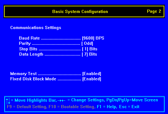
Serial Port 1 Settings
These parameters allow you to set the baud rate, parity, stop bit and data length for
serial port 1.
Use the up and down arrow keys to select the parameter you want to
change, then use the left and right arrow keys to scroll through the possible values until
you reach the correct one.
The default values for the port are 9600 baud, odd parity, 1 stop bit
and 7 bit data.
Memory Test
The system performs a RAM test during Power On Self Test (POST). Setting this parameter to
disable bypasses the RAM test.
Fixed Disk Block Mode
This option can enhance fixed disk drive performance, depending on the fixed disk used in
the system.
Use the up and down arrow keys to move around the screen, and the left
and right arrow keys to alter the settings. There is a second page of Basic System
Configuration, which is accessed using the PgDn key.
 
Advanced System Configuration
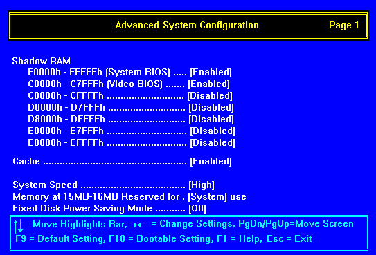
In this screen the F9 key can be used to return all configuration
options, except Memory at 15MB-16MB, to the factory defaults. The default values are those
shown in the screen above.
The F10 key can be used to disable all shadow RAM and the cache, to set
system speed to low and turn fixed disk power saving off. These settings are the least
likely to cause problems with older, speed sensitive, software, or expansion cards
designed for previous generations of personal computers.
Shadow RAM
System and video BIOS
The system and video BIOS on the motherboard is stored in ROM which has long access times.
Enabling shadow RAM enhances the performance of the system by copying the system and/or
video BIOS into RAM.
By copying the BIOS into RAM the system takes advantage of the shorter
access times of RAM. An additional benefit is that shadowed ROM spaces are cached gaining
a further performance advantage.
ISA bus (C8000h - EFFFFh)
BIOS on any expansion cards is stored in ROM which has long access times. Enabling BIOS
shadowing enhances performance by copying the contents of the ROM into RAM. By copying the
BIOS into RAM the system takes advantage of the shorter access times of RAM. Only enable
shadow RAM for ISA bus address ranges that contain adapter BIOS.
Cache
Enabling this option disables the processor internal cache, and, if fitted, the external
cache. There should normally be no reason to disable this cache, it will result in a
performance decrease.
Some old software which is speed sensitive may not work properly with
the cache enabled. This problem in uncommon, and this option is provided as a safety net.
System Speed
This parameter allows you to slow the ISA bus to 8MHz.
This may be useful if you have an old expansion card that will not
operate with the ISA bus running at higher speed.
Only select low if you have a problem with an expansion card.
You can also use the CTRL+ALT++ key combination to toggle between high
and low speed.
Memory at 15MB - 16MB
This parameter allows the memory address range from 15MB to 16MB to be reserved for use by
memory on an ISA expansion card.
Fixed Disk Power Saving Mode
This option allows you to set the hard disk drive to switch to standby mode after
a period of inactivity. The period of inactivity is adjustable from 1 to 18 minutes.
 
System Security
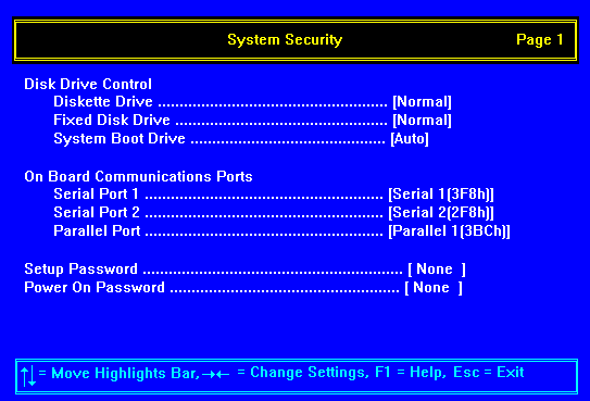
Disk Drive Control
The disk drive parameters allow you to independently control access to hard and floppy
disk drives, and to restrict which drives are bootable.
Diskette Drive / Fixed Disk Drive
These parameters can be set to normal, write protect or disable. In normal mode the
affected drive can perform both read and write operations. Write protect blocks all
attempts to write to the drive, only read operations are permitted. If disable is selected
both read and write operations are inhibited.
Warning
Write protect inhibits write accesses through the BIOS. Therefore write protect only works
for operating systems which use the BIOS to access the drives, specifically DOS. Write
protect mode will not work for operating systems which do not use the BIOS calls to access
the drives.
System Boot Drive
This parameter can be set to Auto, C: or A:. In auto mode the system looks for a diskette
in drive A: and, if a system diskette is present, boots from that. If drive A: is empty
the system boots from drive C: (first hard disk drive).
If A: is selected the system will only boot from a system diskette in
drive A:, if C: is selected the system will only boot from drive C:.
I/O Ports
Serial Ports
These options allow each of the 2 serial ports to be disabled, or to be configured as
COM1, COM2, COM3 or COM4 with the corresponding address given below.
Port Start Address
COM1 3F8h
COM2 2F8h
COM3 3E8h
COM4 2E8h
Note:
The two serial ports must be set to different COM ports. Attempting to configure both
serial ports to the same COM port will result in one port being disabled.
Parallel Port
This option allows the parallel port to be disabled, or to be configured as parallel port
1, 2, or 3 with the corresponding address given below.
Parallel Port Start Address
1 3BCh
2 378h
3 278h
SETUP Password
This option allows you to set a password for the SETUP utility. When this option is in
operation only people who know the password can run the SETUP utility and reconfigure the
system.
To enable the SETUP Password move the highlight bar to Setup Password,
and press the left and right arrow key. You will then be requested to enter a password of
up to seven characters, once you have keyed the password and pressed the return key you
will be asked to retype the password to ensure accuracy.
Power-On Password
This option allows you to set a system password. When this option is in operation
only people who know the password can use the system.
To enable the power-on password move the highlight bar to Power-On
Password, and press the left or right arrow key. You will then be requested to enter a
password of up to seven characters, once you have keyed the password and pressed the
return key you will be asked to retype the password to ensure accuracy.
When the power-on password is enabled you are prompted to enter it every
time the system boots.
To disable the password, at the prompt, enter the current password
followed by a forward slash (/). To change the existing password enter the current
password followed by a forward slash (/) and the new password.
 
Interrupts, DMA, Memory & I/O Ports
 
Interrupts (IRQ)
Interrupts |
Default Function |
Notes |
IRQ 0 |
System time |
This cannot be used by an expansion card. |
IRQ 1 |
Keyboard |
This cannot be used by an expansion card. |
IRQ 2 |
Slave interrupt cont. |
This cannot be used at the same time as IRQ9. |
IRQ 3 |
Serial port 2 |
Available if this feature is disabled in SETUP. |
IRQ 4 |
Serial port 1 |
Available if this feature is disabled in SETUP. |
IRQ 5 |
Not used |
|
IRQ 6 |
Floppy disk controller |
This cannot be used by an expansion card. |
IRQ 7 |
Parallel port |
IRQ 7 is not normally used, and can be used by expansion cards |
IRQ 8 |
Real time clock |
This cannot be used by an expansion card. |
IRQ 9 |
Not used |
|
IRQ 10 |
Not used |
|
IRQ 11 |
Not used |
|
IRQ 12 |
Mouse |
This cannot be used by an expansion card. |
IRQ 13 |
Co processor |
This cannot be used by an expansion card. |
IRQ 14 |
Hard disk controller |
This cannot be used by an expansion card. |
IRQ 15 |
|
|
 
DMA Channels
Channel |
Default Function |
Notes |
DMA 0 |
Not used |
|
DMA 1 |
Not used |
|
DMA 2 |
Floppy disk controller |
This cannot be used by an expansion card. |
DMA 3 |
Not used |
|
DMA 4 |
Not used |
|
DMA 5 |
Not used |
|
DMA 6 |
Not used |
|
DMA 7 |
Not used |
|
 
Memory Map
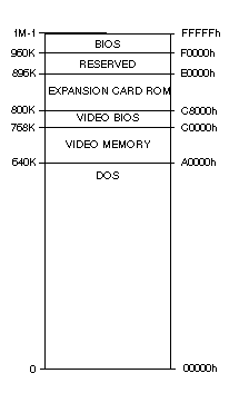
 
I/O Ports
I/O ports (Hex) |
Used by |
000 - 01F |
DMA controller 1 |
020 - 027 |
Interrupt controller 1 |
030 - 037 |
Interrupt controller 1 |
040 - 047 |
System timer |
050 - 057 |
System timer |
060 - 06F |
Keyboard controller |
070 - 07F |
Real time clock, NMI mask |
080 - 09F |
DMA page register |
0A0 - 0BF |
Interrupt controller 2 |
0C0 - 0DF |
DMA controller 2 |
0F0, 0F1 |
Math coprocessor |
0F8 - 0FF |
Math coprocessor |
1F0 - 1F8 |
Hard disk drive controller |
178, 17A |
Power-saving port |
278 - 27F |
Parallel port 2 |
2F8 - 2FF |
Serial port 2 |
35F, 36F |
Power-saving port |
37F |
Reserved |
378 - 37F |
Parallel port 1 |
3F0 - 3F7 |
Diskette drive controller |
3F8 - 3FF |
Serial port 1 |
 
Front Panel Cable
Connections
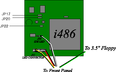
 

|


