XEN-PC (Jade)
Motherboard (Rev 1.6.2)
RAM CONFIGURATION
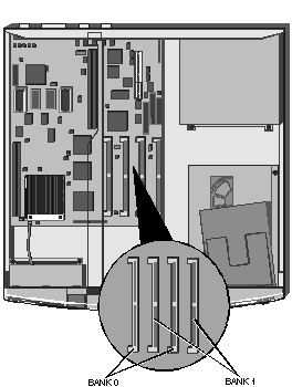
The motherboard is fitted with sockets for four SIMM's. The sockets
support standard 70ns 4Mbyte (1M x 32), 8Mbyte (2M x 32), 16Mbyte (4M x 32) and 32Mbyte
(8M x 32) SIMM's, and are arranged in two pairs.
Each pair of sockets forms a single 64-bit wide memory bank. If a bank
is populated it must always be fitted with a matched pair of SIMM's, giving upgrade
capacities of 8, 16, 32 and 64Mbytes. Optimum performance is achieved when all four
sockets are populated with matched SIMM's.
Each bank can be populated, or fitted with a pair of matching SIMM's of
any of the capacities supported. The two banks are numbered 0 and 1 (see diagram below),
and the sockets have text alongside them identifying the banks.
Location of Banks 0 and 1
 
Ethernet Options
| IBM Token Ring card |
XB42148 |
| IBM Token Ring card Remote Boot ROM |
SN47602 |
| 3Com Ethernet card, thin/thick (3C503) |
XB50902 |
| 3Com Ethernet card, UTP/Thick (3C503B-TP) |
XB50901 |
| 3Com triple-combo (thin/thick/UTP) Ethernet card, (3C509) |
XB51623 |
| 3Com AUI to UTP Transceiver (3C583) |
XB50900 |
 
Disk Drives
 
Jumper Settings
J2 CMOS

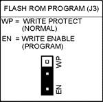
J3 FLASH ROM Program
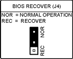
J4 BIOS Recover
J9 VGA Enable
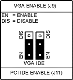
J11 PCI IDE Enable

J12 ISA IDE Interrupt
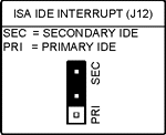
J13 Cache Module Type
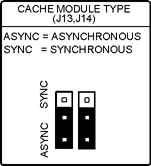
J14 Cache Module Type

J15 Floppy Controller
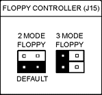
 
Additional Options
AdLOC Security card XB001
Modems
TripleX modem card V21, V22 & V23 XB8762
Graphics Cards for PCI Motherboards
Diamond Viper PCI graphics card add in XB53632
Matrox MGA Ultima PCI graphics card add in XB53738
 
Rear Panel
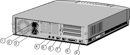
 
CMOS
To discharge CMOS refer to jumper J2 CMOS.
To change CMOS Setup ALT-S needs to pressed at boot
up.
 
CMOS Setup
Configuration
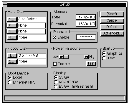
If during the Power On Self Test routine <ALT-S> is pressed the
following screen will appear. It will also appear if the configuration of the machine has
changed since the last power on.
Hard Disk
The hard disk option group provides a button and text for each of the four disk drives
that the motherboard can support. The computer provides slots for two IDE hard disk
drives, in this application drives three and four will never be fitted.
The buttons access a screen which allows you to select whether or not
the hard disk is fitted
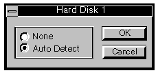
If the drive is fitted Auto detect must be selected. This allows the
motherboard to automatically determine the size and type of hard disk.
If the drive is not fitted None must be selected. Drives three and four
will always be set to None.
Floppy Disk
The floppy disk option group provides a button and text for each of the two floppy disk
drives that the computer can support.
The buttons access a screen which allows you to select the type of
floppy disk.
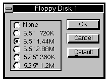
As standard floppy disk 1 is a 3.5" 1.44M drive. Floppy disk 2, if
fitted, is a 5.25" 1.2M drive. If no second floppy is fitted floppy disk 2 should be
set to None.
The other floppy drive types are supported by the motherboard, but not
currently supplied.
Boot Device
Local
This should be selected if the computer is to boot from an internal hard disk or floppy
drive.
Ethernet RPL
If the computer is connected to an Ethernet network using an on-board interface, and it is
to boot remotely from a server using the RPL (Remote Program Load) scheme, enable this
option.
Memory
The memory text box displays a count of the amount of memory installed in the system. The
contents of the text box cannot be edited and is displayed for information only
Password
The system supports a power-on password. If enabled this password must be entered every
time the system is powered up or rebooted.
When the password is enabled the text box can be selected and a password
entered. The password has a minimum length of 1 character and a maximum of 7 characters.
Power-on Sound
This option is greyed out unless the system is equipped with on-board audio. When enabled
the computer provides an audible indication that the system has been switched on.
Volume
The volume control adjusts the output level of the Power-on Sound. Use it to adjust the
volume to suit the computers location.
Test
Use the Test button to preview the Power-On Sound to ensure that you have set it to a
suitable level.
Monitor Type
There are three option buttons in this group: SVGA, VGA/EVGA and EVGA (high refresh). The
three options alter the timings of video signals provided by the video connector to suit a
variety of different types of monitor.
It is important to ensure that you have made the correct selection.
SVGA
This option should be chosen for SVGA monitors. These are monitors that support 800 x 600
non-interlaced and 1024 x 768 interlaced video modes in addition to standard VGA modes.
VGA/EVGA
This option should be chosen for VGA monitors, and for EVGA monitors to run at normal
refresh rates, typically 60Hz. EVGA monitors support 800 x 600 and 1024 x 768
non-interlaced video modes in addition to standard VGA modes.
VGA monitors will not display resolutions greater than 640 x 480 correctly.
EVGA (high refresh)
This option can be used if your EVGA monitor supports high refresh rates. If this option
is chosen: 640 x 480, 800 x 600 and 1024 x 768 display modes use high refresh rates,
typically 72Hz.
The video timings in these high refresh rate modes are VESA compatible. VGA and SVGA
monitors will not work if this option is selected.
Startup
Graphics
When graphics is selected the initial boot screen is displayed in graphical format.
Text
When text is selected a text based boot screen is used.
 
Advanced Options
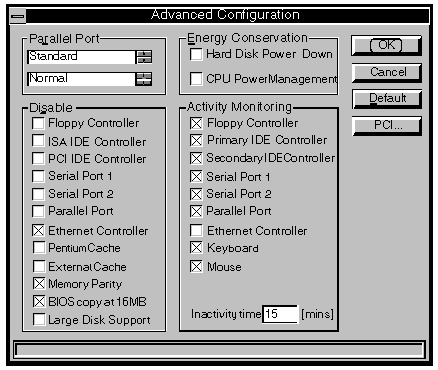
This button activates a screen of advanced options. Many of the options
affect the operation of the motherboard, and should only be changed by the technically
competent user.
Parallel Port Operational Mode
The parallel port supports standard (AT compatible, uni-directional), EPP (Enhanced
Parallel Port), and ECP (Extended Capabilities Port) modes of operation.
Parallel Port I/O Address
The parallel port can be configured to three different I/O port address's, they are Normal
(3BCh), Alternate 1 (378h), and Alternate 2 (278h). Note that EPP is not possible at 3BCh.
Floppy Disk Controller
Checking this box disables the motherboard floppy drive interface. Since all systems are
supplied fitted with at least one diskette drive you should not normally disable the
interface.
Disabling the floppy drive interface in SETUP disables the relevant
motherboard hardware and frees the interrupt and the DMA channel associated with it.
IDE Controllers
Checking these boxes disables the corresponding motherboard IDE interface. You should only
disable an interface that you are sure does not have a drive attached.
Disabling an interface in SETUP disables the relevant motherboard
hardware and frees the interrupt associated with it.
The PCI IDE controller option is greyed if the controller is not fitted.
Serial Port 1, 2 and Parallel Port
Checking this box disables the port associated with that box. You should only disable a
port if you are sure that you do not want to use it.
Disabling a port in SETUP disables the relevant motherboard hardware and
frees the interrupt associated with the port.
Ethernet Controller
Checking this box disables a motherboard Ethernet controller. You should only disable the
Ethernet controller if you are not using it.
This option is normally greyed out.
Disabling the Ethernet controller in SETUP disables the motherboard
hardware and frees the interrupt associated with the controller.
Pentium Cache
Checking this box disables the cache memory inside the processor. There should normally be
no reason to disable the processor cache, it will result in a performance decrease.
Some old software which is speed-sensitive may not work properly with
the cache enabled. This problem is uncommon, and this option is provided as a safety net.
External Cache
Checking this box disables the external cache, the cache outside the processor. There
should be no reason to disable this cache, it will result in a performance decrease.
Some old software which is speed-sensitive may not work properly with
the cache enabled. This problem is uncommon, and this option is provided as a safety net.
If your computer is not equipped with the external cache this option
will be greyed out.
Memory Parity
This box disables memory parity checking.
Memory parity checking is a mechanism that guards against errors, it is normally enabled.
BIOS Copy at 16MB
In an ISA compatible system a copy of the system BIOS appears at 16Mbytes. Checking this
box removes that copy of the system BIOS from the memory map.
In systems fitted with up to 16Mbytes of RAM the box can be either
checked, or unchecked, it is unlikely to have a significant effect.
In systems fitted with more than 16Mbytes of RAM, the box must be
checked.
Large Disk Support
Large disk support is always enabled.
Large Disk Support allows the full capacity of hard disk drives with more than 1024
cylinders to be accessed.
This feature does not affect drives with less than 1024 cylinders, but
the disable option may be used in the future for reasons of compatibility.
Hard Disk Power Down
When this check box is selected, hard disk drives change into a low power consumption mode
after 20 minutes of inactivity.
A hard disk drive in the low power mode will automatically resume normal
operation on the next hard disk access.
CPU Power Management
When this check box is not selected the Activity monitoring option group is greyed out.
Selecting this check box enables the Activity monitoring option group.
When the CPU inactivity timer is enabled, periods of system inactivity
are monitored. If the system is inactive for longer than a user defined period, the
processor is switched to a lower clock frequency, reducing power consumption.
The system continues to operate normally at the lower clock frequency,
but performance is reduced.
Once operating at the lower frequency the processor is returned to
normal operation whenever activity occurs at any of the options selected in the Activity
monitoring option group.
Floppy Controller
When this option is selected any attempt to access a floppy drive will cause the processor
to resume normal operation.
Primary IDE Controller
When this option is selected any attempt to access a drive connected to the Primary IDE
interface will cause the processor to resume normal operation.
This option may be of value if you are sharing a drive connected to this
interface across a network. In this case you may choose to enable the option to ensure
that drive accesses over the network cause the processor to resume normal operation.
Secondary IDE Controller
When this option is selected any access to a drive connected to the secondary IDE
interface will restore normal operation. In this application the secondary IDE interface
is normally used for ATA-PI CD-ROM drives.
This option may be of value if you are sharing an ATI-PI CD-ROM drive
across a network. In this case you may choose to enable the option to ensure that any
drive access over the network cause the processor to resume normal operation.
Serial Port 1
When this option is selected any activity on Serial Port 1 will cause the processor to
resume normal operation.
If you have a modem or fax/modem, or a printer which you are sharing on
a network, connected to the serial port, you may wish to enable this option.
Serial Port 2
When this option is selected any activity on Serial Port 2 will cause the processor to
resume normal operation.
If you have a modem or fax/modem, or a printer which you are sharing on
a network, connected to the serial port, you may wish to enable this option.
Parallel Port
When this option is selected any activity to the Parallel port will cause the processor to
resume normal operation.
If you have a printer connected to the parallel port which you are
sharing on a network you may wish to enable this option.
Ethernet Controller
This option is normally greyed out.
When this option is selected any activity to a motherboard Ethernet controller will cause
the processor to resume normal operation.
Enabling this option is not recommended, messages broadcast on the
network will almost invariably prevent the processor ever entering its low power mode.
Keyboard
This option is greyed out and is always selected. Pressing any key returns the processor
to normal operation.
Mouse
When this option is selected moving the mouse or pressing a mouse button will cause the
processor to resume normal operation.
If you use the mouse a great deal you may wish to select this option.
Inactivity Time
This text box is used to specify the period of inactivity after which the processor is
switched to a slower clock speed.
Valid values are 0 to 99 minutes.
 
Advanced Configuration - PCI
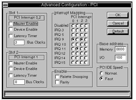
PCI configuration is performed automatically by an
auto-configuration utility in the BIOS. Under normal circumstances it is unlikely that you
will have to alter any of the settings on this screen.
PCI IDE Speed
This option group provides two option buttons to select whether the PCI IDE interface
operates in a fast mode, or a standard mode.
The default setting is fast, and in this mode the PCI IDE interface
maximises the performance of the hard disk drive subsystem.
The alternative setting is Normal, and in this mode the PCI IDE
interface runs in a slower mode which ensures compatibility with older hard disk drives.
PCI Interrupt
This text indicates which PCI interrupt, or interrupts, each PCI expansion card uses.
PCI interrupts must be connected to ISA interrupts. A full description
of this process is given in the description of Interrupt Routing.
Device Enable
When selected enables the card in the affected PCI slots.
Master Enable
When selected enables the card in the affected slot to operate as bus master on the PCI
bus.
Latency Timer
This limits the period, after the bus controller has revoked control, for which a bus
master can continue the current transfer. When this option is not checked the latency
timer uses a default value obtained from the PCI card.
When this option is checked the latency timer is set to the number of
bus clock cycles in the text box below. The accepted range of values is from 0 to 256 in
steps of eight.
Unless the documentation supplied with a PCI card recommends changing
this setting, or you encounter problems, there should be no need to check this option.
Palette Snooping
This option allows a PCI video card to monitor the colour palette of the motherboard video
controller.
Parity Checking
Enables parity checking on the PCI bus.
Base Address
These two text boxes indicate the first addresses in memory and I/O spaces that the PCI
auto-configuration utility can allocate to PCI cards.
Interrupt Routing
These option buttons are used to connect PCI interrupts to ISA interrupts.
The PCI bus provides four level sensitive interrupts (0, 1, 2, 3). These
interrupts are shareable, that is two or more PCI devices can use the same interrupt.
Each PCI interrupt in use must be connected to a single ISA interrupt.
This routing process is known as routing and is carried out on the motherboard.
An ISA interrupt can have more than one PCI interrupt routed to it. An
ISA interrupt that has one or more PCI interrupt, which in use, routed to it cannot be
used by an ISA device.
If a motherboard Ethernet interface is fitted it must use PCI interrupt
3.
ISA interrupts which are in use by the system are greyed out.
 
Interrupts, Memory &
I/O Ports
Interrupts
Memory
I/O Ports
 
Interrupts (IRQ)
Interrupts |
Default Function |
Notes |
IRQ 0 |
System time |
This cannot be used by an expansion card. |
IRQ 1 |
Keyboard |
This cannot be used by an expansion card. |
IRQ 2 |
Cascade |
This cannot be used by an expansion card. |
IRQ 3 |
Serial port 2 |
Each of the serial ports, can be individually |
IRQ 4 |
Serial port 1 |
disabled using SETUP. |
IRQ 5 |
Not used |
|
IRQ 6 |
Floppy disk controller |
This cannot be used by an expansion card. |
IRQ 7 |
Parallel port |
IRQ 7 is not normally used, and can be used by expansion cards |
IRQ 8 |
Real time clock |
This cannot be used by an expansion card. |
IRQ 9 |
Not used |
|
IRQ 10 |
Not used |
|
IRQ 11 |
Not used |
|
IRQ 12 |
Mouse |
This cannot be used by an expansion card. |
IRQ 13 |
Co processor |
This cannot be used by an expansion card. |
IRQ 14 |
Hard Disk Controller |
This cannot be used by an expansion card. |
IRQ 15 |
Secondary hard disk |
This can be used if the interface is not used or disabled. |
 
Memory Map
 
I/O Ports
I/O ports (Hex) |
Used by |
000 - 01F |
DMA controller 1 |
020 - 027 |
Interrupt controller 1 |
030 - 037 |
Interrupt controller 1 |
040 - 047 |
System timer |
050 - 057 |
System timer |
060 - 06F |
Keyboard controller |
070 - 07F |
Real time clock,NMI mask |
080 - 09F |
DMA page register |
0A0 - 0BF |
Interrupt controller 2 |
0C0 - 0DF |
DMA controller 2 |
0F0, 0F1 |
Math coprocessor |
0F8 - 0FF |
Math coprocessor |
1F0 - 1F8 |
Hard disk drive controller |
178, 17A |
Power-saving port |
278 - 27F |
Parallel port 2 |
2F8 - 2FF |
Serial port 2 |
35F, 36F |
Power saving port |
37F |
Reserved |
378 - 37F |
Parallel port 1 |
3F0 - 3F7 |
Diskette drive controller |
3F8 - 3FF |
Serial port 1 |
928 - 92F |
Motherboard control ports |
 
LED Cable Connections
 

|


