
 |
|
 |
|
||||||||||||||||||||||||||||||||||||||||||||||||||||||||||||||||||||||||||||||||||||||||||||||||||||||||||||||||||||||||||||||||||||||||||||||||||||||||||||||||||||||||||||||||||||||||||||||||||||||||||||||||||||||||||||||||||||||||||||||||||||||||||||||||||||||||||||||||||||||||||||||||||||||||||||||||||||||||||||||||||||||||||||||||||||||||||||||||||||||||||||||||||||||||||||||||||||||||||||||||||||||||||||||||||||||||||||||||||||||||||||||||||||||||||||||||||||||||||||||||||||||||||||||||||||||||||||||||||||||||||||||||||||||||||||||||||||||||||||||||||||||||||||||||||||||||||||||||||||||||||||||||||||||||||||||||||||||||||||||||||||||||||||||||||||||||||||
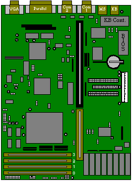 |
 |
RAM CONFIGURATION (only the following configurations are supported)
Bank 0 |
Bank 1 |
Bank 2 |
Bank 3 |
Total |
4 MB |
- |
- |
- |
4 MB |
4 MB |
4 MB |
- |
- |
8 MB |
8 MB |
- |
- |
- |
8 MB |
4 MB |
4 MB |
4 MB |
- |
12 MB |
8 MB |
4 MB |
- |
- |
12 MB |
4 MB |
4 MB |
4 MB |
4 MB |
16 MB |
8 MB |
4 MB |
- |
4 MB |
16 MB |
8 MB |
8 MB |
- |
- |
16 MB |
16 MB |
- |
- |
- |
16 MB |
16 MB |
4 MB |
- |
- |
20 MB |
16 MB |
4 MB |
- |
4 MB |
24 MB |
16 MB |
8 MB |
- |
- |
24 MB |
4 MB |
4 MB |
4 MB |
16 MB |
28 MB |
16 MB |
8 MB |
4 MB |
- |
28 MB |
16 MB |
16 MB |
- |
- |
32 MB |
16 MB |
4 MB |
- |
16 MB |
36 MB |
4 MB |
4 MB |
16 MB |
16 MB |
40 MB |
16 MB |
8 MB |
16 MB |
- |
40 MB |
16 MB |
16 MB |
16 MB |
- |
48 MB |
4 MB |
16 MB |
16 MB |
16 MB |
52 MB |
16 MB |
16 MB |
16 MB |
16 MB |
64 MB |
| IBM Token Ring card | XB42148 |
| IBM Token Ring card Remote Boot ROM | SN47602 |
| 3Com Ethernet card, thin/thick (3C503) | XB50902 |
| 3Com Ethernet card, UTP/Thick (3C503B-TP) | XB50901 |
| 3Com triple-combo (thin/thick/UTP) Ethernet card, (3C509) | XB51623 |
| 3Com AUI to UTP Transceiver (3C583) | XB50900 |
| MB | Make | Model | Type | Part Number |
| 210 | Quantum | LPS 210 AT | IDE | SU53985 |
| 270 | Quantum | LPS 270 AT | IDE | SU52577 |
| 270 | Quantum | MV 270AT | IDE | SU53459 |
| 365 | Quantum | LT 365 AT | IDE | SU54080 |
| 540 | Quantum | LPS 540 AT | IDE | SU52578 |
| 540 | Quantum | MV540AT | IDE | SU53460 |
| 640 | Quantum | FB 640 AT | IDE | SU56070 |
| 730 | Quantum | LT 730 AT | IDE | SU54082 |
| Tape | ||||
| 150 | Archive | Viper150 | SCSI | SU50638 |
| 525 | Archive | Viper525 | SCSI | SU50639 |
| 1.3GB | Archive | Python | SCSI | SU50640 |
| 2-8GB | Archive | DDS-DC | SCSI | SU52593 |
| Floppy | ||||
| 2 MB | Sony | MPF520-1 | 3.5" | |
| Panasonic | JU-475-4 | 5.25" | SU52600 | |
| CD-ROM | ||||
| Sony | CDU31A-02 | SLCD | SA50158 | |
| Sony | CDU31A-03 | SLCD | SA52537 | |
| Sony | CDU33A-01 | SLCD | SU53071 | |
| Sony | CDU55E-01 | IDE | SU54021 | |
| Sony | CDU76E-01 | IDE | SU54763 | |
| Sony | CDU561 | SCSI | XB51703 |
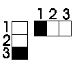 Jumper
numbering looking from the front of the machine.
ECP DMA Channel
| JP1 | JP10 | |
| 1 - 2 | 1 - 2 | DMA 1 |
| 2 - 3 | 2 - 3 | DMA 3 (default) |
VGA Reset
| JP2 | 1 - 2 | Hardware Control |
| 2 - 3 | Software Control (default) |
Password Setting
| JP3 | 1 - 2 | Checking |
| 2 - 3 | Bypass (default) |
BIOS Vendor
| JP4 | 1 - 2 | OEM BIOS (default) |
| 2 - 3 | Acer BIOS |
VGA Select
| JP5 | 1 - 2 | Mono/Com 1 Boot |
| 2 - 3 | Normal Colour (default) |
On-board SMC665
| JP6 | 1 - 2 | Disable |
| 2 - 3 | Enable (default) |
On-board VGA (CL543x)
| JP9 | 1 - 2 | Disable |
| 2 - 3 | Enable (default) |
System Clock
| JP11 | 1 - 5 | 25 MHz |
| 2 - 6 | 33 MHz (default) | |
| 3 - 7 | 40 MHz | |
| 4 - 8 | 50 MHz |
VESA/PCI Selection
| JP12 | JP16 | |
| 1 - 2 | 1 - 2 | PCI System |
| 2 - 3 | 2 - 3 | VESA System (default) |
CPU Type
i486* |
AMD |
M7 |
P24D |
|
JP13 |
2 - 3 |
2 - 3 |
1 - 2 |
2 - 3 |
JP14 |
2 - 3 |
1 - 2 |
2 - 3 |
2 - 3 |
JP15 |
2 - 3 |
1 - 2 |
Open |
2 - 3 |
JP19 |
2 - 3 |
2 - 3 |
2 - 3 |
1 - 2 |
JP20 |
Open |
Open |
Close |
Open |
JP23 |
Open |
Open |
Open |
Close |
| * - Default |
| JP18 | 1 - 2 | TI CPU |
| 2 - 3 | Others (default) |
| JPX1 | 1 - 2 | AMD 3.3V CPU Only |
| 2 - 3 | Others (default) |
System Speed
| JP17 | 1 - 2 | 40 / 50 MHz |
| 2 - 3 | 25 / 33 MHz (default) |
On-board Local Bus IDE
| JP21 | 1 - 2 | Disable |
| 2 - 3 | Enable (default) |
HDD I/O Address
| JP22 | 1 - 2 | Disable |
| 2 - 3 | Enable (default) |
Cache Data Sizing
128K |
256K* |
512K |
|
JP24 |
1 - 2 |
1 - 2 |
2 - 3 |
JP25 |
1 - 2 |
2 - 3 |
2 - 3 |
JP26 |
2 - 3 |
2 - 3 |
2 - 3 |
JP28 |
1 - 2 |
2 - 3 |
1 - 2 |
* - Default |
|||
DX4-100 Clock Mul.
| JP27 | 1 - 2 | 5 x External Clock |
| 2 - 3 | 2 x External Clock | |
| Open | 3 x External Clock (default) |
| JP29 | 2 - 3 | Default |
External SMM
| JP30 | Open | Disable |
| Close | Enable (default) |
Reset / External SMM
| JP31 | 1 - 2 | External SMM |
| 2 - 3 | Reset (default) |
AMD CPU Clock Mul.
| JPX2 | 1 - 2 | 2 x External Clock |
| 2 - 3 | 3 x External Clock | |
| Open | Default |
CPU VCC
| JPX4 | 1 - 2 | 3.3V M7/AMD CPU |
| 2 - 3 | Others (default) |
| AdLOC Security card | XB001 |
| 0Kb to 256Kb Cache RAM Upgrade | SH52451 |
| 128Kb to 256Kb Cache RAM Upgrade | SH53372 |
Cache upgrade |
Number of chips in kit |
Where to fit them |
From none to 256 Kb |
9 |
Cache sockets 1 to 9 |
From none to 128 Kb |
5 |
Cache sockets 1 to 5 |
From 128 Kb to 256 Kb |
4 |
Cache sockets 6 to 9 |
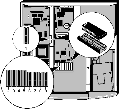
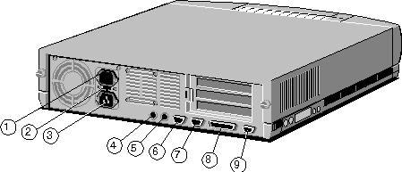
| 1 - AC Power Outlet | 4 - Keyboard Port | 7 - Serial Port 2 |
| 2 - Voltage Selection Switch | 5 - Mouse Port | 8 - Parallel Port |
| 3 - AC Power Inlet | 6 - Serial Port 1 | 9 - Monitor Port |
To discharge CMOS remove the Lithium battery as shown below. To enter CMOS Setup press the CTRL-ALT-ESC keys.
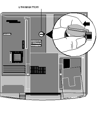
LITHIUM BATTERY
This battery has a life of 3 years, and is user replaceable when discharged.
The XEN-PC uses a 3V lithium battery, used in calculators and other small, battery powered
electronic items. The battery used in the XEN-PC is a BP2335 or equivalent.
INTERRUPTS, DMA, MEMORY and I/O PORTS
Interrupts
DMA
Memory Map
I/O Ports
Interrupts |
Default Function |
Notes |
IRQ 0 |
System time |
This cannot be used by an expansion card. |
IRQ 1 |
Keyboard |
This cannot be used by an expansion card. |
IRQ 2 |
Slave interrupt cont. |
This cannot be used at the same time as IRQ9. |
IRQ 3 |
Serial port 2 |
Available if this feature is disabled in SETUP. |
IRQ 4 |
Serial port 1 |
Available if this feature is disabled in SETUP. |
IRQ 5 |
Not used |
|
IRQ 6 |
Floppy disk controller |
This cannot be used by an expansion card. |
IRQ 7 |
Parallel port |
IRQ 7 is not normally used, and can be used by expansion cards |
IRQ 8 |
Real time clock |
This cannot be used by an expansion card. |
IRQ 9 |
Not used |
|
IRQ 10 |
Not used |
|
IRQ 11 |
Not used |
|
IRQ 12 |
Mouse |
This cannot be used by an expansion card. |
IRQ 13 |
Co processor |
This cannot be used by an expansion card. |
IRQ 14 |
Hard disk controller |
This cannot be used by an expansion card. |
IRQ 15 |
Enhance IDE |
Not fitted |
Channel |
Default Function |
Notes |
DMA 0 |
Not used |
|
DMA 1 |
SDLC |
|
DMA 2 |
Floppy disk controller |
This cannot be used by an expansion card. |
DMA 3 |
Not used |
|
DMA 4 |
Not used |
|
DMA 5 |
Not used |
|
DMA 6 |
Not used |
|
DMA 7 |
Not used |
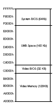
I/O ports (Hex) |
Used by |
000 - 01F |
DMA controller 1 |
020 - 021 |
Interrupt controller 1 |
040 - 05F |
Timer |
060 - 06F |
Keyboard controller |
070 - 07F |
Real time clock, NMI mask |
080 - 09F |
DMA page register |
0A0 - 0BF |
Interrupt controller 2 |
0C0 - 0DF |
DMA controller 2 |
0F0, 0F1 |
Math coprocessor |
0F8 - 0FF |
Math coprocessor |
1F0 - 1F7 |
Hard disk drive controller |
200 - 207 |
Game I/O |
278 - 27F |
Parallel port 2 |
2B0 - 2DF |
Alternate EGA |
2F8 - 2FF |
Serial port 2 |
378 - 37F |
Parallel port 1 |
3B0 - 3BF |
Monochrome display and printer adapter |
3B4, 3B5, 3BA |
Video subsystem |
3C0 - 3CF |
EGA |
3C6 - 3C9 |
Video DAC |
3D0 - 3DF |
Colour graphic adapter |
3F0 - 3F7 |
Diskette drive controller |
3F8 - 3FF |
Serial port 1 |
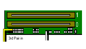
When you invoke BIOS Setup the main menu contains several choices as shown below:
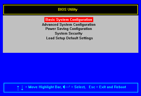
Basic System Configuration uses a two page screen that allows you to modify settings for date and time, drive types, serial port characteristics and so on.
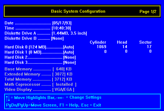
Date
The BIOS Setup utility shows the system date in month/day/year format.
To alter the date:
1. Use the UP ARROW and DOWN ARROW keys to select the field you want to change (month, day
or year).
2. Use the LEFT ARROW and RIGHT ARROW keys to scroll through the field's possible values
until you reach the correct one.
Once the correct date is set you should not need to set it again. The computer accounts for leap years automatically.
Time
The BIOS Setup utility shows the system time in 24-hour hours:minutes:seconds format.
To alter the time:
1. Use the UP ARROW and DOWN ARROW keys to select the field you want to change (hour,
minutes or seconds).
2. Use the LEFT ARROW and RIGHT ARROW keys to scroll through the field's possible values
until you reach the correct one.
Once the correct time is set you should not need to set it again, except at the start and end of daylight saving time.
Diskette Drive
The computer supports up to two diskette/floppy-disk drives. Both have several possible
settings:
None
360 Kbyte, 5.25 inch
1.2 Mbyte, 5.25 inch
720 Kbyte, 3.5 inch
1.44 Mbyte, 3.5 inch
2.88 Mbyte, 3.5 inch
Diskette drive A is always a 1.44 Mbyte, 3.5" drive.
Diskette drive B (if fitted) will usually be a 1.2 Mbyte, 5.25" floppy disk drive.
Hard Disks
The motherboards two ATA/IDE (AT Attachment Intergrated Drive Electronics) interfaces
support a total of four drives (that is, two drives per interface). However, the computer
itself can accommodate at most two IDE hard disk drives plus one ATA removable-media
drive. The hard disk drives should be connected to the primary interface, and any
removable-media drive connected to the secondary interface.
Configuring hard disk drives
It is important that you select the correct drive type for each hard disk drive. The BIOS
Setup utility provides three methods of specifying drive type information:
The simplest method is to set Hard Disk 0 (or Hard Disk 1) to "Auto", meaning "auto-detect". The BIOS interrogates the drive and, if it is recognised, automatically sets the drive type information. Most drives can be interrogated in this way.
You can make a selection from one of the BIOS Setup's predefined drive
types, numbered 1 to 99.
You can manually enter parameters by setting the drive type to "User" and
pressing the ENTER key. Use the LEFT ARROW and RIGHT ARROW keys to move along the line of
parameters, entering Cylinder, Head and Sector numbers as you go. When you have finished,
press ESC.
If auto-configuration is not possible, drive type information can be
obtained from your supplier, the drive manufacturer's documentation, or the label attached
to the drive.
The Hard Disk 0 and Hard Disk 1 entries are greyed-out if you enable the AutoConfiguration Mode option. In this mode the BIOS
always auto-configures the drive types.
Caution
If the drive is already formatted, selected the wrong drive type may result in loss of
data. If the drive is not formatted, selecting the wrong drive type may mean that the
drive's full capacity is not used. We recommend that the first time you turn on the
computer you invoke BIOS Setup and make a note of the drive type parameters. This will
ensure that you can always re configure the drive type correctly.
Configuring an ATA-PI CD-ROM drive
Assuming that the CD-ROM is connected to the secondary ATA/IDE interface, as recommended,
set the Hard Disk 2 drive type to "CD".
If there is no ATA device fitted, the Hard Disk 2 drive type should be "None".
Obviously, Hard Disk 3 drive type should always be "None".
System Memory
The BIOS automatically detects the total amount of system memory and shows this in the
BIOS Setup utility. The three system memory parameters (Base, Extended and Total) are
displayed for information only and are not user-adjustable. If you install additional
memory, the BIOS updates the memory parameters accordingly.
| Parameter | Meaning |
| Base Memory | The first 640 Kbytes of system memory. Also known as conventional memory. |
| Extended Memory | The amount of memory over and above the first 1 Mbyte of system memory. |
| Total Memory | The total amount of memory, excluding the 384 Kbyte upper memory area (typically reserved for system and video BIOS, and expansion card memory). |
Math Coprocessor
The BIOS automatically detects the presence of a coprocessor and shows this in the BIOS
Setup utility.
Video Display
The BIOS automatically detects the video mode of your primary display and shows this in
the BIOS Setup utility.
Basic System Configuration Page 2
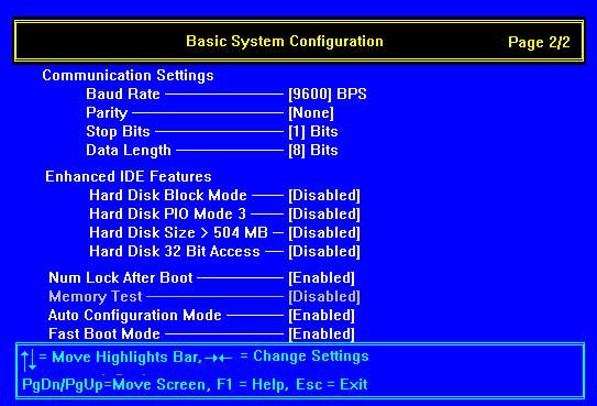
Communication Settings
This option allows you to set the baud rate, parity, stop bit and data length for serial
port 1.
The default values for the port are 9600 baud, odd parity, 1 stop bit and 7 bit data word.
Enhanced IDE Features
These options control a set of performance-enhancing features for hard disk drives. Most
drives nowadays support these features, although some depend on what operating system you
are using.
Hard Disk Block Mode
This option enhances performance for drives that support block mode. When enabled, it
allows the computer to read and write more information at one time. (If the computer no
longer boots after enabling this option, it is likely that the master hard disk does not
support this function. Run BIOS Setup and disable the option.)
Hard Disk PIO Mode 3
This option enhances performance for drives that support polled input/output (PIO) modes.
PIO mode 3 is the fastest mode. Disable this option if the master hard disk does not
support this function.
Hard Disk Size > 504 MB
Enable this feature if the computer has a hard disk with a capacity greater than 504
megabytes and you are using the MS-DOS/Windows operating system. For hard disks of lesser
capacity, or if you are using another operating system, this option should be disabled.
Hard Disk 32-Bit Access
This option enhances performance for drives that support it. However, the feature
currently works only under the MS-DOS/Windows and NetWare operating systems. If your
operating system or hard disk does not support 32-bit access, this option should be
disabled.
Num Lock After Boot
If this option is enabled, the numeric keypad on the keyboard is automatically set to
provide numeric keys rather than cursor control keys at the boot time. The default setting
is disabled.
Memory Test
If this option is enabled, the POST (power-on self test) routines test the system memory
at boot time.
If you enable the Fast Boot Mode option, Memory Test is disabled automatically, and the entry greyed-out so that you cannot re-enable it without first disabling Fast Boot Mode.
Auto Configuration Mode
If this option is enabled, certain BIOS Setup options are returned to their default
settings and/or greyed-out so that they cannot be altered:
The Hard Disk 0 and Hard Disk 1 entries in the Basic System Configuration screen are set to "Auto" (meaning "auto-detect").
Shadow RAM (for system and video BIOS), Internal Cache and External Cache are all "Enabled", and System Speed is set to "High" in the Advanced System Configuration screen.
Auto Configuration Mode is enabled by default.
Fast Boot Mode
If this option is enabled, certain BIOS Setup options are set to ensure that the computer
boots as quickly as possible and then greyed-out so that they cannot be altered until Fast
Boot Mode is disabled again.
Memory Test is set to "Disabled" in the Basic System
Configuration screen.
Shadow RAM (for system and video BIOS), Internal Cache and External Cache are all
"Enabled", and System Speed is set to "High" in the Advanced System
Configuration screen.
Fast Boot Mode is enabled by default.
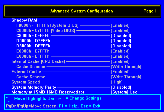
Advanced System Configuration allows you to modify settings for shadow RAM, internal and external caches, system speed and so on.
Shadow RAM
This option allows you to shadow the computer's system and/or video BIOS read-only memory
(ROM). You can also shadow individual 32 Kbyte (8000h) areas of expansion card ROM
addressed between C8000h and EFFFFh.
To "shadow" ROM means to copy its contents into the computer's system or random-access memory (RAM). This is beneficial for two reasons: ROM has (relatively) long access times and the processor can access RAM faster than ROM; second, the contents of RAM can be cached for even greater performance.
Note that the two 32 Kbyte areas from E0000h to E7FFFh and E8000h to EFFFFh cannot be shadowed independently of the system BIOS ROM.
Internal Cache (CPU Cache)
This option enables or disables the internal memory cache (that is, the cache within the
processor itself). There should normally be no reason to disable this cache, as this will
result in poorer performance. Some old software which is speed sensitive may not work
properly with the cache enabled, but this is very rare nowadays.
External Cache
This option enables or disables the external memory cache (if any). If an external cache
is fitted, there should normally be no reason to disable it.
An external cache is an area of dedicated memory with significantly faster access times than the computer's system memory. A cache controller ensures that the cache always contains a copy of the most recently accessed areas of system memory, so that the processor is able to read it much more quickly.
An external cache is sometimes called a second-level cache, to distinguish it from the internal or first-level cache contained within the processor itself.
Cache Scheme
If the internal/external cache is enabled, and the processor allows, you can set the cache
scheme to "Write Back" or "Write Through".
These are two alternative ways the cache controller can work. The write-back method updates the cache but not the system memory when there is a write instruction; it updates the memory only when there is an inconsistency between the cache and the memory. The write-through method updates both the cache and the memory whenever there is a write instruction.
The write-back method is quicker, but the write-through method is slightly safer (there is less chance of the contents of the cache getting out of step with the contents of system memory). For most everyday computing needs, you should set the Cache Scheme to "Write Back".
Some types of processor have a fixed cache scheme (usually write-through) that you can't change. In this case the Cache Scheme option is greyed-out.
System Speed
This option allows you to set the speed of the ISA (expansion card) bus.
| Setting | Meaning |
| High | ISA bus runs at 10 MHz. This is the default setting. |
| Low | ISA bus runs at 8 MHz. Select this only if you have an old expansion card that will not operate with the ISA bus running at the higher speed. |
System Memory Parity
This option enables or disables parity checking of random-access memory for those systems
that support it (most systems do not).
Memory at 15MB-16MB
This option allows the memory address range from 15 Mbyte to 16 Mbyte (F00000h to FFFFFFh)
to be reserved for use by system memory or an ISA expansion card.
| Setting | Meaning |
| System | The range F00000h to FFFFFFh is used for system memory (if more than 15 Mbytes is fitted). |
| Add-on Card | The range F00000h to FFFFFFh is used for expansion card memory. |
Power Saving Configuration allows you to configure the power management features which make the computer Energy Star compliant.
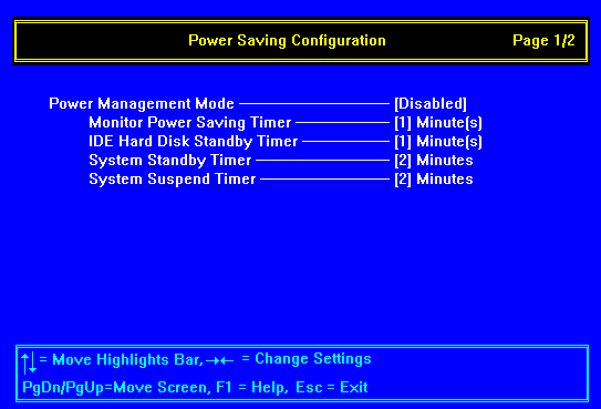
Power Management Mode
Power Management Mode may be enabled or disabled. If enabled, the following options apply.
Note that these options are not affected by the Load System Default Settings option of
BIOS Setup.
Monitor Power-Saving Timer
This option is intended to be used only with monitors that support Display Power
Management Signalling (DPMS).
You can specify an inactivity timeout between 1 and 15 minutes. If the display does not change in this time, the monitor enters a power-saving Suspend mode. The monitor returns to full power when you move the mouse or press any keyboard key.
IDE Hard Disk Standby Timer
This option is intended to be used only with hard disk drives that support ATA/IDE Power
Mode commands.
You specify an inactivity timeout between 1 and 15 minutes. If there are no hard (fixed) disk read/writes during this time, the drive enters a power-saving Standby mode (the drive is spun down). The drive is spun up again when it is next accessed. Depending on the drive, it can take several seconds for the drive to spin up.
System Standby Timer
This option is a combination of the first two options, but extended to cover system
activity.
You can specify a system inactivity timeout of up to 120 minutes. If there is no system activity during this time, the monitor enters Suspend mode and the hard disk drive(s) enter Standby mode. The monitor and hard disk drive(s) return to normal operation when you move the mouse or press any keyboard key.
System Suspend Timer
This option provided the maximum power savings.
You can specify a system inactivity timeout of up 120 minutes. If there is no system activity during this time:
The monitor enters the DPMS Off mode (that is, the monitor is
effectively turned off).
The hard disk drive(s) enter Standby mode (they are spun down).
Several motherboard components are put into a power-saving mode.
The processors' internal clock is stopped.
The system returns to normal operation when you move the mouse or press any keyboard key.
Power Saving Configuration page 2
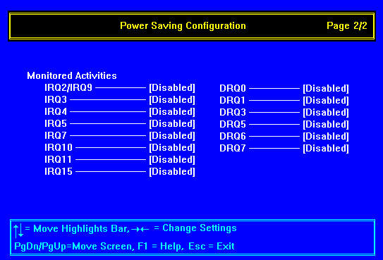
Monitored Activities
You can use these options to enable or disable system activity monitoring and so specify
what you mean by "system inactivity" in relation to the System Standby and
System Suspend modes. You can tell the BIOS to monitor selected interrupt requests (IRQs)
and direct memory access requests (DRQs). Activity on any one of the enabled IRQs or DRQs
resets the system inactivity timer and keeps the system out of the power-saving modes.
System Security allows you to configure the motherboard security features. These include setting passwords, restricting access to diskette and hard disk drives, and configuring the serial and parallel ports.
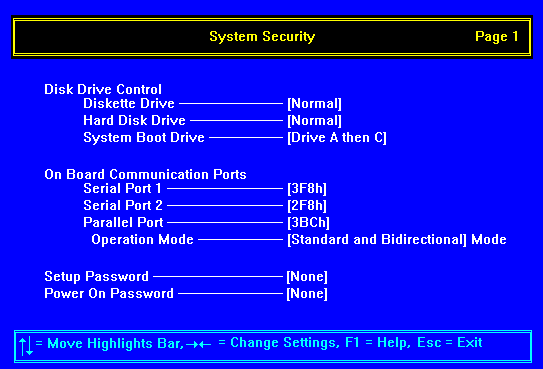
Disk Drive Control
These options allow you to control access to diskette/floppy disk drives and hard disk
drives, and to specify where the BIOS should look for an operating system when the
computer boots. Use these options to reduce the risk of computer viruses being introduced
into the computer.
Diskette Drive and Hard Disk Drive
Both these options have the same four possible settings:
| Setting | Meaning |
| Normal | The computer can read from and write to the drive. |
| Write Protect All Sectors | The computer can read from but not write to the drive. |
| Write Protect Boot Sector | The computer can read from the drive, and write to all sectors except the boot sector. |
| Disable | The computer can neither read from nor write to the drive. |
Note that write-protection inhibit write accesses through the BIOS, therefore these options work only for operating systems which use the BIOS to access the drives (for example, MS-DOS).
System boot drive
This option specifies where the BIOS looks for an operating system.
| Setting | Meaning |
| Drive A then C | The BIOS looks first for a system diskette in drive A and, if one is present, boots from that. If drive A is empty the system attempts to boot from drive C (the first hard disk drive). If there is no active, bootable partition on drive C, the computer cannot boot locally. |
| Drive C then A | The BIOS looks first for an active bootable partition on drive C and, if present, boots from that. If none exists, the BIOS looks for a system diskette in drive A. If drive A is empty, the computer cannot boot locally. |
| Drive A | The BIOS looks for a system diskette in drive A and, if one is present, boots from that. If drive A is empty, the computer cannot boot locally. |
| Drive C | The BIOS looks for an active, bootable partition on drive C and, if present, boots from that. If there is none, the computer cannot boot locally. |
Note that if the BIOS finds a non-system diskette in drive A, you will be prompted to replace it.
On-Board Communication Ports
Serial Port Base Addresses
These options allow each of the two serial ports to be disabled, or to configured as COM1,
COM2, COM3 or COM4.
| Setting | Meaning |
| 3F8h | COM1 at I/O port address 3F8h |
| 2F8h | COM2 at I/O port address 2F8h |
| 3E8h | COM3 at I/O port address 3E8h |
| 2E8h | COM4 at I/O port address 2E8h |
| Disabled | Serial port is disabled |
The two serial ports must be set to different COM ports. Attempting to configure both serial ports to the same COM port will result in one port being disabled.
Parallel Port Base Address
This option allows the parallel port to be disabled, or to configured with the I/O port
base addresses shown below.
| Setting | Meaning |
| 3BCh | I/O port address 3BCh (usually LPT1) |
| 378h | I/O port address 378h (usually LPT2) |
| 278h | I/O port address 278h (usually LPT3) |
| Disabled | Parallel port is disabled |
If you install an expansion card with a port that uses the same I/O port address as the parallel port, the parallel port is disabled automatically.
Parallel Port Operation Mode
This option allows you to set the mode of the parallel port:
| Setting | Meaning |
| Enhanced Parallel Port (EPP) | Allows bi-directional parallel port operation at maximum speed. Compatible with the Enhanced Parallel Port standard. |
| Extended Capabilities Port (ECP) | Allows the parallel port to operate in bi-directional mode and at a speed higher than the nominal maximum data transfer rate, Compatible with the Microsoft/Hewlett Packard Extended Capabilities Port standard. |
| Standard and Bi-direction | Allows normal speed operation in both directions. |
Passwords
These password options are intended for computers that lack more sophisticated security
systems. You should not attempt to use these options on an Apricot XEN-PC LS computer with
a built-in LOC Technology security system.
Some caution is required when using these options. At the factory, a jumper on the motherboard is set to "Bypass" password checking. With the jumper in this position, you can define passwords, but the computer will not prompt for them. To enable password checking you must move the jumper to the "Check" position.
Password Setting
| JP3 | 1 - 2 Checking |
| 2 - 3 Bypass (default) position. |
Setup Password
This option allows you to set a password for the BIOS Setup utility. When this option is
in operation only people who know the password can run the BIOS Setup utility and re
configure the system. A small "key" icon appears in the top left hand corner of
the screen. The person wanting to run BIOS Setup must then type the password and press
ENTER. Three attempts are permitted, after which the computer is disabled and must be
turned off then on again.
Power-On Password
This option allows you to set a password that is requested every time the computer is
turned on or rebooted. Only people who know the password can use the computer. A small
"key" icon appears in the top left-hand corner of the screen. The person wanting
to use the computer must then type the password and press ENTER. Three attempts are
permitted, after which the computer is disabled and must be turned off then on again.
Load Setup Default Settings resets all settings (except power management and security) back to their default settings. The default settings are the ones shown on the example screens shown. You can use this option if the battery sustaining CMOS memory loses power, or if the memory itself becomes corrupted.
![]()