 |
|
 |
|
|||||||||||||||||||||||||||||||||||||||||||||||||||||||||||||||||||||||||||||||||||||||||||||||||||||||||||||||||||||||||||||||||||||||||||||||||||||||||||||||||||||||||||||||||||||||||||||||||||||||||||||||||||||||||||||||||||||||||||||||||||||||||||||||||||||||||||||||||||||||||||||||||||||||||||||||||||||||||||||||||||||||||||||
 |
 |
The motherboard is fitted with sockets for four SIMM's these allow system RAM to be expanded to up to 128Mbytes using standard 32 or 36 bit, 72 pin, 70ns SIMM's.
The SIMM sockets are located at the front of the motherboard, beneath the 5.25" drive bay.
SIMM's must be installed in pairs. Each pair is called a bank, bank 0 is formed by the pair of sockets nearest the hard drive bay, bank 1 is formed by the pair nearest the processor. 32 and 36 bit SIMM's can be mixed, provided they are the same in each bank.
Apricot supplies 4Mb, 8Mb, 16Mb and 32Mb SIMM's, giving upgrade capacities of 8, 16, 32 and 64Mbytes. Any combination of these capacities is possible, using any capacity in either of the two pairs.
Possible SIMM Memory Combinations
Bank 0 |
Bank 1 |
Total System Memory |
8MB |
Empty |
8MB |
8MB |
8MB |
16MB |
16MB |
Empty |
16MB |
16MB |
8MB |
24MB |
16MB |
16MB |
32MB |
32MB |
Empty |
32MB |
32MB |
8MB |
40MB |
32MB |
16MB |
48MB |
32MB |
32MB |
64MB |
64MB |
Empty |
64MB |
64MB |
8MB |
72MB |
64MB |
16MB |
80MB |
64MB |
32MB |
96MB |
64MB |
64MB |
128MB |
| IBM Token Ring card | XB42148 |
| IBM Token Ring card Remote Boot ROM | SN47602 |
| 3Com Ethernet card, thin/thick (3C503) | XB50902 |
| 3Com Ethernet card, UTP/Thick (3C503B-TP) | XB50901 |
| 3Com triple-combo (thin/thick/UTP) Ethernet card, (3C509) | XB51623 |
| 3Com AUI to UTP Transceiver (3C583) | XB50900 |
| MB | Make | Model | Type | Part Number |
| 270 | Quantum | LPS 270 AT | IDE | SU52577 |
| 270 | Quantum | MV 270AT | IDE | SU53459 |
| 365 | Quantum | LT365AT | IDE | SU54080 |
| 540 | Quantum | LPS 540 AT | IDE | SU52578 |
| 540 | Quantum | MV540AT | IDE | SU53460 |
| 730 | Quantum | LT 730 AT | IDE | SU54082 |
| 1,000 | IBM | DPEA 31080 | IDE | XB54020 |
| Tape | ||||
| 150 | Archive | Viper150 | SCSI | SU50638 |
| 525 | Archive | Viper525 | SCSI | SU50639 |
| 2-8GB | Archive | DDS-DC | SCSI | SU52593 |
| Floppy | ||||
| 2 MB | Sony | 3.5" | ||
| Panasonic | 5.25" | SU52600 | ||
| CD-ROM | ||||
| Sony | CDU31A-02 | SLCD | SA50158 | |
| Sony | (Dual Scan) | CDU31A-03 | SLCD | SA52537 |
| Sony | CDU33A-01 | SLCD | SU53071 | |
| Sony | CDU55E-01 | IDE | SU54021 | |
| Sony | CDU561 | SCSI | XB51703 |
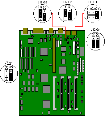
| Jumper | Function | Default |
| J7 A1 (1) | Reserved | Not Fitted |
| Jumper | Function | Default |
| J7 A1 (2) | 66MHz / 60MHz | 66MHz |
| Jumper | Function | Default |
| J12 G1 (1) | Clear / don't clear CMOS | Don't clear CMOS |
| NOTE:- Change the jumper then power the machine on and off to drain CMOS | ||
| Jumper | Function | Default |
| J12 G1 (2) | Clear / don't clear password | Don't clear password |
| Jumper | Function | Default |
| J12 G3 (1) | Flash normal / flash recovery | Flash normal |
| Jumper | Function | Default |
| J12 G3 (2) | Enable / disable flash updates | Disable flash updates |
| Jumper | Function | Default |
| J12 G5 (1) | Monochrome / colour | Colour |
| Jumper | Function | Default |
| J12 G5 (2) | Enable / disable entry | Enable entry into SETUP |
| Jumper | Function | Default |
| J13 H1 (1) | 5.25V Processor voltage | Not Fitted |
| J13 H1 (2) | Reserved | Not Fitted |
| J13 H1 (3) | 5V Processor voltage | Fitted |
| Jumper J13 H1 must have a jumper clip fitted either in position 1 or position 3, never both. | ||
AdLOC Security card XB001
Other Memory Expansion
1Mb to 2Mb Video RAM upgrade XB53733
Modems
TripleX modem card V21, V22 & V23 XB8762
Graphics Cards for PCI Motherboards
Diamond Viper PCI graphics card add in XB53632
Matrox MGA Ultima PCI graphics card add in XB53738

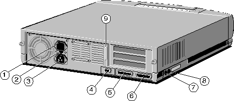
| 1 - AC Power Outlet | 4 - Keyboard Port | 7 - Serial Port 2 |
| 2 - Voltage Selection Switch | 5 - Mouse Port | 8 - Parallel Port |
| 3 - AC Power Inlet | 6 - Serial Port 1 | 9 - Monitor Port |
To discharge CMOS refer to jumper J12 G1 (1) (see Note below)
| NOTE: | Jumper Function Default J12 G1 (1) Clear / don't clear CMOS Don't clear CMOS |
| NOTE:- Change the jumper then power the machine on and off to drain CMOS |
INTERRUPTS, MEMORY and I/O PORTS
Interrupts (IRQ)
Interrupts |
Default Function |
Notes |
IRQ 0 |
System time |
This cannot be used by an expansion card. |
IRQ 1 |
Keyboard |
This cannot be used by an expansion card. |
IRQ 2 |
Cascade |
This cannot be used by an expansion card. |
IRQ 3 |
Serial port 2 |
Each of the serial ports, can be individually |
IRQ 4 |
Serial port 1 |
disabled using SETUP. |
IRQ 5 |
Not used |
|
IRQ 6 |
Floppy disk controller |
This cannot be used by an expansion card. |
IRQ 7 |
Parallel port |
IRQ 7 is not normally used, and can be used by expansion cards |
IRQ 8 |
Real time clock |
This cannot be used by an expansion card. |
IRQ 9 |
Not used |
|
IRQ 10 |
Not used |
|
IRQ 11 |
Not used |
|
IRQ 12 |
Mouse |
This cannot be used by an expansion card. |
IRQ 13 |
Co processor |
This cannot be used by an expansion card. |
IRQ 14 |
Secondary hard disk |
This is available for use unless an IDE device is connected to port. |
IRQ 15 |
Hard disk controller |
This cannot be used by an expansion card. |
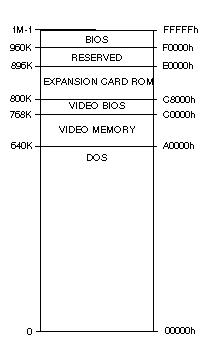
Memory Map

I/O Ports
I/O ports (Hex) |
Used by |
000 - 00F |
DMA controller |
020 - 021 |
Interrupt controller 1 |
040 - 043 |
System timer |
048 |
System timer |
060 - 064 |
Keyboard controller |
070 - 078 |
Real time clock, NMI mask |
080 - 08F |
DMA page register |
0A0 - 0BF |
Interrupt controller 2 |
0C0 - 0DF |
DMA controller 2 |
0F0 |
Math co processor |
1F0 - 1F7 |
Hard disk drive controller |
278 - 27F |
Parallel port 3 |
2F8 - 2FF |
Serial port 2 |
378 - 37F |
Parallel port 2 |
3B8 - 3BF |
Parallel port 1 |
3E8 - 3EF |
Serial port 3 |
3F0 - 3F7 |
Diskette drive controller |
3F8 - 3FF |
Serial port 1 |
![]()