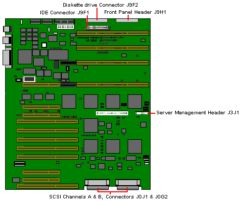
Shogun Xxpress Motherboard
PS3 Connector J9B2 and PS4 Connector J9C2
| Pin |
Signal |
Pin |
Signal |
| 1 |
+5 V |
4 |
GND |
| 2 |
+5 V |
5 |
GND |
| 3 |
+5 V |
6 |
GND |
| |
|
|
|
| Pin |
Signal |
Pin |
Signal |
| 1 |
+5.1 V |
4 |
GND |
| 2 |
GND |
5 |
GND |
| 3 |
+12 V |
6 |
GND |
PS5 Connector J9D1
| Pin |
Signal |
Pin |
Signal |
| 1 |
N/C |
10 |
N/C |
| 2 |
N/C |
11 |
N/C |
| 3 |
N/C |
12 |
3.3 VRD |
| 4 |
Sense+ |
13 |
3.3 V |
| 5 |
GND |
14 |
3.3 V |
| 6 |
GND |
15 |
3.3 V |
| 7 |
GND |
16 |
3.3 V |
| 8 |
GND |
17 |
3.3 V |
| 9 |
GND |
18 |
3.3 V |
PS1 and PS2, Connector J9D2
| Pin |
Signal |
PS1 Colour |
| 1 |
PWRGOOD |
Orange |
| 2 |
+5 V |
Red |
| 3 |
+12 V |
Yellow |
| 4 |
-12 V |
Blue |
| 5 |
GND |
Black |
| 6 |
GND |
Black |
| 7 |
GND |
Black |
| 8 |
GND |
Black |
| 9 |
-5 V |
White |
| 10 |
+5 V |
Red |
| 11 |
+5 V |
Red |
| 12 |
+5 V |
Red |
Fan Connectors
| Pin |
Signal |
| 1 |
GND |
| 2 |
+12 V |
| 3 |
Fan sense |
SCSI Controller Activity Light
Connectors J4J2 & J1J2
| Pin |
Signal |
Pin |
Signal |
| 1 |
Return |
3 |
Hard disk active |
| 2 |
Hard disk active |
4 |
Return |
PS6 Connector J1A1
| Pin |
Signal |
Pin |
Signal |
| 1 |
GND |
4 |
+3.3 V |
| 2 |
GND |
5 |
+3.3 V |
| 3 |
GND |
6 |
+3.3 V |
 
System Management Controller Board
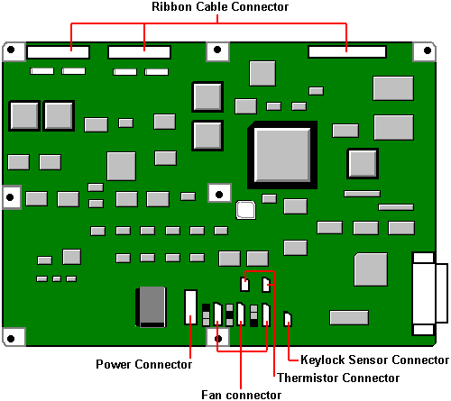
 
Motherboard Power Distribution Panel

 
Hard Drives
| MB |
Make |
Model |
Type |
Part Number |
| 1,000 |
IBM |
DHFS S1S |
FAST/WIDE SCSI (See Note below) |
HA55475 |
| 2,000 |
IBM |
DHFS S2S |
FAST/WIDE SCSI (See Note below) |
HA55476 |
| 4,000 |
IBM |
DHFS S4S |
FAST/WIDE SCSI (See Note below) |
HA55477 |
| TAPE |
|
|
|
|
| 4-16GB |
Conner |
CTD8000R-S |
SCSI |
SU54778 |
| 16-64GB |
Conner |
CTL96GR-S |
SCSI |
HA55473 |
| 20-40GB |
Quantum |
DLT4000 |
SCSI |
HA55474 |
| CD-ROM |
|
|
|
|
|
Sony |
CDU76S |
SCSI |
|
NOTE: FAST & WIDE SCSI (Rel 1.8.1)
SCSI was originally developed as a bus that transferred up to 5 Mbytes
per second: this bus was 8 bits wide. The transfer rate was doubled to 10 Mbytes per
second and the term FAST was introduced. The 8 bit bus was then developed into a 16 bit
bus which doubled the transfer rate to 20 Mbytes per second and this development was
called WIDE. Hence the term FAST & WIDE SCSI on Shogun.
80 Pin SCSI Drive Technology
The Shogun uses an SCA connector (Single Connector Attachment) on the
SCSI disk drive interface. This 80 pin SCA connector includes the 16 bit wide SCSI bus
plus the DC power and ID addressing, allowing optimum engineering access for the Shogun
HOT PLUG technology.
 
Jumper Settings
Configuration Switch Block S8C1

| Switch |
Position |
Function |
| S8C1-1 |
On
Off * |
Clear CMOS
Protect CMOS |
| S8C1-2 |
On
Off * |
Clear Password
Enable Password |
| S8C1-3 |
On *
Off |
Enable flash write
Disable flash |
To clear CMOS move switch to the Clear position
then power the machine on and off and then move switch back to the Protect position.
Jumper J4H1, TDV

| Jumper |
Pins |
Description |
| J4H1, TDV |
1 - 2 Enable * |
Enables the CPU 2 (secondary) slot to accept TDV modules |
| |
2 - 3 Disable |
Prevents the CPU 2 slot from accepting TDV modules (allows X-series
modules) |
Jumper J6A1, Video Sleep

| Jumper |
Pins |
Description |
J6A1,
Video Sleep |
1 - 2
REG 46E8 |
Selects address register at 46E8H |
| |
2 - 3
REG 3C3 * |
Selects address register at 03C3H |
Jumper J7C1, Program Boot Block

| Jumper |
Pins |
Description |
J7C1, Program
Boot Block |
1 - 2 Disable * |
Prevents writing to the BIOS boot block |
| |
2 - 3 Enable |
Enables writing to the BIOS boot block |
Jumper J7D2, Boot Block

| Jumper |
Pins |
Description |
J7D2,
Boot Block |
1 - 2 Disable * |
Normal BIOS boot block |
| |
2 - 3 Enable |
Recovery BIOS boot block |
Jumper J9B1, FD1 Floppy Driver 1

| Jumper |
Pins |
Description |
J9B1, FD1
Floppy
Driver 1 |
1 - 2
1.44MB * |
Disables 2.88MB size detection |
| |
2 - 3 2.88MB |
Enables automatic size detection |
Jumper J9C1, FD0 Floppy Driver 0

| Jumper |
Pins |
Description |
J9C1, FD0
Floppy
Driver 0 |
1 - 2
1.44MB * |
Disables 2.88MB size detection |
| |
2 - 3 2.88MB |
Enables automatic size detection |
Jumper J9C3, PWR CTRL

| Jumper |
Pins |
Description |
J9C3,
PWR CTRL |
1 - 2 Enable * |
Disables RTC power control |
| |
2 - 3 Disable |
Enables power supply maintenance voltage control using the RTC |
 
Using the Front Panel
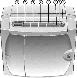
2 - POWER ON - Press this button to switch the system
on from Standby Mode. The Power LED will light up and the system will initiate its boot
sequence. Diagnostic codes, expressed as hexadecimal numbers, will appear as a matter of
course on the LCD screen on the Front Panel. What happens after this depends on how your
Shogun has been configured, i.e. which operating system or other software may be
installed.
4 - STANDBY - After you have instructed all network
users to close their applications down and log off the network, hold this button down for
a specific period of time before the system initiates a shutdown sequence to Standby Mode.
The system will display the code 1200 on the LCD and sound a tone. Continue to hold down
the STANDBY button until the tone stops, at which time the shutdown sequence begins. In
Standby Mode, the mains electricity supply keeps the battery pack fully charged, but there
is no DC power supplied to the system.
Press STANDBY and CONTROL simultaneously to cancel the current shutdown
sequence.
3 - CONTROL - Press this button to silence alarms and
clear LCD display codes that are produced because of internal errors and power failures.
Pressing Control at the end of firmware initialisation forces the system
to execute the code of the EPROM instead of the Flash ROM, even if the version in the
Flash is newer than that of the EPROM. This still allows you to boot from EPROM if there
is something wrong with the Flash code.
5 - RESET - Press this button to initiate a hardware
reset, but only if it is absolutely necessary. The LCD will display 1400. You must hold
the button down until the accompanying tone stops sounding.
Press RESET and CONTROL simultaneously to cancel the current reset
sequence.
Special Button Functions
Pressing Standby, Control and Reset simultaneously while the front drive
bay door is unlocked switches the system into a mode in which these three buttons have
special functions. The LCD displays 8888 to indicate this mode.
 STANDBY or
RESET - Pressing one of these buttons initiates a memory dump to the central processing
unit by activating and then deactivating the Non-Maskable Interrupt (NMI) signal via the
diagnostic processor. You can then use the appropriate function of the network operating
system to examine the contents of the dump. STANDBY or
RESET - Pressing one of these buttons initiates a memory dump to the central processing
unit by activating and then deactivating the Non-Maskable Interrupt (NMI) signal via the
diagnostic processor. You can then use the appropriate function of the network operating
system to examine the contents of the dump.
 CONTROL -
Pressing this button initialises the modem, which is connected to the SMC serial port on
the backplane of the Shogun. If the modem initialisation is successful, the LCD displays
the code 0000. If the initialisation is unsuccessful, the LCD displays 0F4D or 0F4E. CONTROL -
Pressing this button initialises the modem, which is connected to the SMC serial port on
the backplane of the Shogun. If the modem initialisation is successful, the LCD displays
the code 0000. If the initialisation is unsuccessful, the LCD displays 0F4D or 0F4E.
 STANDBY + RESET
- Pressing these buttons simultaneously clears the LCD and then releasing them executes an
independent Front Panel System Controller (FPSC) reset. This would only be necessary if a
major problem or error had occurred in the system. STANDBY + RESET
- Pressing these buttons simultaneously clears the LCD and then releasing them executes an
independent Front Panel System Controller (FPSC) reset. This would only be necessary if a
major problem or error had occurred in the system.
If you do not press any buttons for ten seconds, the system returns to
normal mode.
7 - UPS LED
 When this LED
shows steady green, it means that the system is powered by mains electricity and the
batteries are fully charged. When this LED
shows steady green, it means that the system is powered by mains electricity and the
batteries are fully charged.
 Flashing green
means that the system is powered by mains electricity and the batteries are in the process
of charging. This will usually be the case after the system has been without mains
electricity, i.e. disconnecting the plug or a power failure. Flashing green
means that the system is powered by mains electricity and the batteries are in the process
of charging. This will usually be the case after the system has been without mains
electricity, i.e. disconnecting the plug or a power failure.
 Steady amber
indicates that the system is drawing its power off the batteries, i.e. there is no mains
electricity. As soon as mains electricity fails, an alarm sounds. Steady amber
indicates that the system is drawing its power off the batteries, i.e. there is no mains
electricity. As soon as mains electricity fails, an alarm sounds.
 Flashing amber
indicates that the battery pack is about to fail. Flashing amber
indicates that the battery pack is about to fail.
 Off shows that
the batteries are disconnected because the isolation switch on the back of the Shogun is
in the Off position or the system is disconnected from the mains. Off shows that
the batteries are disconnected because the isolation switch on the back of the Shogun is
in the Off position or the system is disconnected from the mains.
8 - POWER LED
 Steady green
means that the system is on. Steady green
means that the system is on.
 Steady amber means that the
system has been locked by the infra-red card. Steady amber means that the
system has been locked by the infra-red card.
 Flashing amber means that the
system is detecting data from the infra-red card. Flashing amber means that the
system is detecting data from the infra-red card.
 
Rear Panel
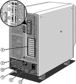
 
CMOS Discharge
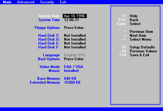
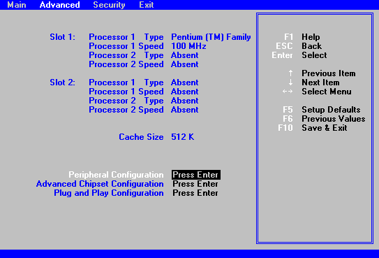
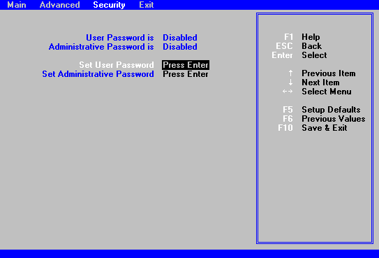
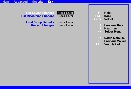
To enter CMOS Setup Press F1 during BOOT. To discharge CMOS use S8C1-1 on the motherboard.
 
I/O Map
0000 - 001F |
DMA Controller 1 |
0020 - 0021 |
Interrupt Controller 1 |
0022 - 0023 |
EISA bridge config. space access ports |
0024 - 0025 |
AIP configuration space access ports |
0026 - 0027 |
Configuration Space Access Ports |
0040 - 005F |
Programmable Timer |
0060, 0064 |
Keyboard Controller |
0061 |
NMI Status & Control Register |
0070 |
NMI Mask (bit 7) & RTC Address (bits 6:0) |
0071 |
Real Time Clock (RTC) |
0080 - 008F |
DMA Low Page Register |
0092 |
System Control Port A (PC-AT control Port) |
00A0 - 00BF |
Interrupt Controller 2 |
00C0 - 00DF |
DMA Controller 2 |
00F0 |
Clear NPX error |
00F8 - 00FF |
x87 Numeric Coprocessor |
0102 |
Video Display Controller |
0170 - 0177 |
Secondary Fixed Disk Controller (IDE) |
01F0 - 01F7 |
Primary Fixed Disk Controller (IDE) |
0200 - 0207 |
Game I/O Port |
0220 - 022F |
Serial Port |
0238 - 023F |
Serial Port |
0278 - 027F |
Parallel Port 3 |
02E8 - 02EF |
Serial Port 2 |
02F8 - 02FF |
Serial Port 2 |
0338 - 033F |
Serial Port 2 |
0370 - 0375 |
Secondary Floppy |
0376 |
Secondary IDE |
0377 |
Secondary IDE / Floppy |
0378 - 037F |
Parallel Port 2 |
03B4 - 03BA |
Monochrome Display Port |
03BC - 03BF |
Parallel Port 1 (Primary) |
03C0 - 03CF |
Enhanced Graphics Adapter |
03D4 - 03DA |
Colour Graphics Controller |
03E8 - 03EF |
Serial Port |
03F0 - 03F5 |
Floppy Disk Controller |
03F6 - 03F7 |
Primary IDE - Sec. Floppy |
03F8 - 03FF |
Serial Port 1 (Primary) |
0400 - 043F |
DMA Controller 1, Extended Mode Registers |
0461 |
Extended NMI / Reset Control |
0462 |
Software NMI |
0464 |
Last EISA Bus master granted |
0480 - 048F |
DMA High Page Register |
04C0 - 04CF |
DMA Controller 2, High Base Register |
04D0 - 04D1 |
Interrupt Controllers 1 & 2 Control Register |
04D4 - 04D7 |
DMA Controller 2, Extended Mode Register |
04D8 - 04DF |
Reserved |
04E0 - 04FF |
DMA Channel Stop Registers |
0678 - 067A |
Parallel Port (ECP) |
0778 - 077A |
Parallel Port (ECP) |
07BC - 07BE |
Parallel Port (ECP) |
0800 - 08FF |
NVRAM |
0C80 - 0C83 |
EISA System Identifier Registers |
0C84 |
Board Revision Register |
0C85 - 0C86 |
BIOS Function Control |
0CF8 |
PCICONFIG_ADDRESS Register |
0CFC |
PCICONFIG_DATA Register |
n000 - n0FF |
EISA Slot n I/O Space |
x100 - x3FF |
ISA I/O slot alias address |
n400 - n4FF |
EISA Slot n I/O Space (n = 1 to 15) |
x500 - x7FF |
ISA I/O slot alias address |
n800 - n8FF |
EISA Slot n I/O space (n = 1 to 15) |
x900 - xBFF |
ISA I/O slot alias address |
nC00 - nCFF |
EISA Slot n I/O Space (n = 1 to 15) |
xD00 - xFFF |
ISA I/O slot alias address |
46E8 |
Video Display Controller |
EISA Slot Assignments
0 |
System Board |
1 - 8 |
EISA expansion boards |
9 - A |
Embedded SCSI |
B |
Memory module |
C |
Memory module (expansion module) |
D |
Primary PCI segment |
E |
CPU1 module |
F |
CPU2 module |
Direct Memory Access Channels
0 |
(add-in board) |
1 |
(add-in board) |
2 |
Diskette drive |
3 |
IDE hard disk drive |
4 |
Reserved |
5 |
(add-in board) |
6 |
(add-in board) |
7 |
(add-in board) |
ISA Interrupts
NMI |
Parity Error |
0 |
Interval timer |
1 |
Keyboard buffer full |
2 |
Reserved, cascade interrupt from slave PIC |
3 |
Onboard serial port B (COM2), if enabled |
4 |
Onboard serial port A (COM1), if enabled |
5 |
Parallel port LPT2, if enabled |
6 |
Onboard diskette (floppy) controller, if enabled |
7 |
Parallel port LPT1, if enabled |
8 |
Real-time clock (RTC) |
9 |
Video |
10 |
COM3; if enabled, it can be set for EISA add-in boards using the SCU |
11 |
COM4; if enabled, it can be set for EISA add-in boards using the SCU
AIC-7870; if enabled, it can be set for EISA add-in boards using the SCU |
12 |
Onboard PS/2 mouse port, if enabled |
13 |
Math coprocessor error |
14 |
IDE hard drive controller, if enabled |
15 |
User definable; using the SCU, it can be set for the following:
 EISA add-in boards EISA add-in boards
 IDE hard drive controller IDE hard drive controller
 onboard video, programmable to 9,
10, 11, or 15 onboard video, programmable to 9,
10, 11, or 15
 onboard SCSI, programmable to 9,
10, 11, or 15 (SCU limits SCSI to three choices) onboard SCSI, programmable to 9,
10, 11, or 15 (SCU limits SCSI to three choices) |
PCI Interrupts
any IRQx |
SCSI channel A INTA |
any IRQx |
SCSI channel B INTA |
any IRQx |
PCI-0 INTA |
any IRQx |
PCI-0 slot B INTA |
any IRQx |
PCI-0 slot x INTB |
any IRQx |
PCI-0 slot A INTA |
any IRQx |
PCI-0 slot B INTA |
any IRQx |
PCI-0 slot C INTA |
any IRQx |
PCI-0 slot x INTB |
any IRQx |
PCI-0 & 1 slot x INTC |
any IRQx |
PCI-0 & 1 slot x INTD |
any IRQ or NMI, or SMI |
INT1 slot MEM1 |
any IRQ or NMI, or SMI |
INT2 slot MEM2 |
 
Uninterruptible Power Supply
The Uninterruptible Power Supply is a self-contained battery-backed unit
which supplies the system unit with all its power requirements. The following is a list of
its major features:
 1000W maximum
total DC output 1000W maximum
total DC output
 Auto-ranging AC input voltage
selection Auto-ranging AC input voltage
selection
 48V DC input from backup
batteries - 3 off 12Ah Sealed Lead Acid batteries in a removable tray 15 minute on
batteries (half load) 36 hour charge time 48V DC input from backup
batteries - 3 off 12Ah Sealed Lead Acid batteries in a removable tray 15 minute on
batteries (half load) 36 hour charge time
 Battery power circuit breaker Battery power circuit breaker
 Constant voltage battery charging
output Constant voltage battery charging
output
 Remote control / monitoring
facility Remote control / monitoring
facility
 Cooling fans mounted on, and
powered from, the power supply Cooling fans mounted on, and
powered from, the power supply
 Compliance with IEC801 Level 4 -
4KV spike (50ns duration, 15ns intervals) not a mains conditioner Compliance with IEC801 Level 4 -
4KV spike (50ns duration, 15ns intervals) not a mains conditioner
 PSU Removal - 2 man job ! PSU Removal - 2 man job !
 
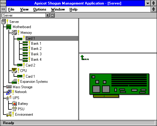
Apricot System Management Application
 
Airflow
Airflow is in through the front
out through the rear
15cm (6") Airspace around the system
5 to 35ºC
10 to 80% humidity
non-condensing
 
On-board Video
Cirrus Logic GD5424, ISA. 512K Video RAM
 
Electrical Safety
Non Standard Power Cable
15A Cable
13A Fuse
IEC 320 C20 Connector
6.5A Maximum Consumption (@ 220V)
15A Protection Circuitry if voltage is low (eg 80V)
Internal Bus Bars
4 @ 5V 120 A
1 @ 12V 40A (50A surge)
Torque setting for bus bar to power supply should be 5N/m²
 
Other Motherboard Connections
 

|


