FT2200 (X1B) Motherboard (Rev 1.12.1)
RAM Configuration
The memory board comes already installed with the basic system. A total
of eight memory banks composed of 16 72-pin SIMM sockets reside on the board. The sockets
accept 8-MB, 16-MB, 32-MB, and 64-MB SIMMs for a maximum of 1 GB memory
configuration.
Adhere to the following rules when you add system memory.
Always install SIMMs from bank 0. You should use the memory banks
consecutively.
Always install SIMMs in pairs to fill up a bank. For example, for a
total memory of 16MB, install two 8-MB SIMMs in a bank. You can not use a single 16-MB
SIMM for a 16-MB configuration.
Use only fast-page mode parity SIMMs.
Install SIMMs of the same capacity in a configuration. For example, do
not mix an 8-MB SIMM with a 16-MB SIMM.

Bank 0 |
Bank 1 |
Bank 2 |
Bank 3 |
Bank 4 |
Bank 5 |
Bank 6 |
Bank 7 |
Total Memory |
8MB*2 |
|
|
|
|
|
|
|
16 MB |
8MB*2 |
8MB*2 |
|
|
|
|
|
|
32 MB |
8MB*2 |
8MB*2 |
8MB*2 |
8MB*2 |
|
|
|
|
64 MB |
8MB*2 |
8MB*2 |
8MB*2 |
8MB*2 |
8MB*2 |
8MB*2 |
8MB*2 |
8MB*2 |
128 MB |
16MB*2 |
|
|
|
|
|
|
|
32 MB |
16MB*2 |
16MB*2 |
|
|
|
|
|
|
64 MB |
16MB*2 |
16MB*2 |
16MB*2 |
16MB*2 |
|
|
|
|
128 MB |
16MB*2 |
16MB*2 |
16MB*2 |
16MB*2 |
16MB*2 |
16MB*2 |
16MB*2 |
16MB*2 |
256 MB |
32MB*2 |
|
|
|
|
|
|
|
64 MB |
32MB*2 |
32MB*2 |
|
|
|
|
|
|
128 MB |
32MB*2 |
32MB*2 |
32MB*2 |
32MB*2 |
|
|
|
|
256 MB |
32MB*2 |
32MB*2 |
32MB*2 |
32MB*2 |
32MB*2 |
32MB*2 |
32MB*2 |
32MB*2 |
512 MB |
64MB*2 |
|
|
|
|
|
|
|
128 MB |
64MB*2 |
64MB*2 |
|
|
|
|
|
|
256 MB |
64MB*2 |
64MB*2 |
64MB*2 |
64MB*2 |
|
|
|
|
512 MB |
64MB*2 |
64MB*2 |
64MB*2 |
64MB*2 |
64MB*2 |
64MB*2 |
64MB*2 |
64MB*2 |
1024 MB |
 
Ethernet Options
| 3Com 10/100 PCI card (3C905TX) |
XB59527 |
| 3Com EISA Combo card (3C900) |
XB59526 |
| 3Com AUI to UTP Transceiver (3C583) |
XB50900 |
| IBM Token Ring LAN card |
XB42148 |
 
Disk Drives
 
Jumper Settings
| Jumper |
Setting |
Function |
Oscillator Freq.
J12 |
Open
1-2
2-3 |
50 MHz
60 MHz
66 MHz (default 166/200MHz) |
| Jumper |
Setting |
Function |
SCSI Feature
J13 |
Open
Closed |
Narrow SCSI
Wide SCSI and narrow SCSI |
| Jumper |
Setting |
Function |
ITP Boundary Scan
J14
J15 |
Open
2-3 |
J14 and J15 are for CPU testing purposes only.
Note: Do not reconfigure. |
| Jumper |
Setting |
Function |
SCSI Termination
J16 |
1-2
2-3 |
SCSI terminator set to On
SCSI terminator switchable to On or Off using the SCSI Setup Utility |
| Jumper |
Setting |
Function |
Password Security
J18 |
1-2
2-3 |
Check password
Bypass password |
| Jumper |
Setting |
Function |
BIOS Logo
J19 |
1-2
2-3 |
For models with Acer BIOS
For models with OEM BIOS |
| Jumper |
Setting |
Function |
Sound Output
J1501 |
1-2
Open |
Enable buzzer output
Disable buzzer output |
Voltage ID Settings
Setting of jumpers J2, J3, J4, and J5 to set CPU1 VRM connector (J1) to
3.3V at 200 MHz.

Setting of jumpers J7, J8, J9, and J10 to set CPU2 VRM
connector (J6) to 3.3V at 200 MHz.

 
SCSI Disk Array Backplane Board
The SCSI disk array backplane board provides a convenient interface
between the SCSI drives and the system board. It includes eight SCSI drive slots to
accommodate the drive trays, two SCSI channels to connect to the system board or SCSI
controller board.
The backplane board has the following major features:
"Hot-swap" feature that allows replacement of a defective hard
drive even while the system is in full operation. This feature requires a RAID controller
board and RAID drivers.
Indicates hard disk drive failure through a front panel board LED
Supports wide SCSI or narrow SCSI devices
Supports mixed configuration of both fast-and-wide (16-bit) and fast-and-UltraWIDE
(32-bit) SCSI drives in a single channel
Allows ‘split’ and ‘combine’ SCSI-channel configurations
SCSI ID strapping that allows wide SCSI HDD ID configuration through the backplane
switches instead of configuring the individual drive IDs
Layout
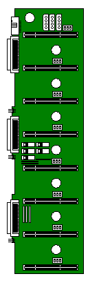
Channel Configuration Switches
Jumper Settings
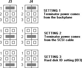
The backplane jumpers J3 and J4 allow you to select the terminator power
source and set drive IDs. J3 supports the four upper drive slots (slots 1, 2, 3, and 4) on
the backplane. J4 supports the four lower drive slots (slots 5, 6, 7, and 8). Default
being setting 2 & 3.
SCSI Hard Disk ID Feature
You can avail of the ID setting feature by configuring the SCSI ID
switches and jumpers J3 and J4 setting 3 on the bakplane board. Normally, you can assign
seven IDs on the backplane (IDs 0 ~ 6). Closing the Setting 3 pins on jumpers J3 and J4
allow you to set eight additional SCSI drive IDs for the SCSI devices installed in the
system.
| |
SCSI
Device ID |
SCSI ID
Switch Setting |

Setting 3 Open
|

Setting 3 Closed |

|
0 |
8 |

|
1 |
9 |

|
2 |
A |

|
3 |
B |

|
4 |
C |

|
5 |
D |

|
6 |
E |

|
|
F |
Channel Configuration
Single-Channel Configuration
In a single-channel configuration, channel 1 supports the SCSI devices
plugged into slots 1 to 8. Set the channel configuration switches to "Combine"
and set the terminators accordingly to achieve a single-channel configuration.
Single-Channel Configuration

Terminator Settings for Single-Channel Configuration
| Terminator |
Setting |
RA1, RA2, RA3
RA4, RA5, RA6 |
Installed
Removed |
Dual-Channel Configuration
In a dual-channel configuration, channel 1 supports the devices in slots
1 to 4, and channel 2 supports the devices in slots 5 to 8. Set the channel configuration
switches to "Split" and set the terminators accordingly to achieve a
dual-channel configuration.
Dual-Channel Configuration
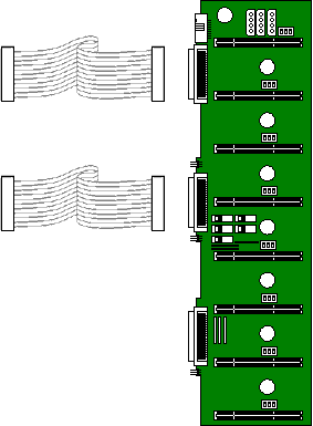
Terminator Settings for Dual-Channel Configuration
| Terminator |
Setting |
RA1, RA2, RA3
RA4, RA5, RA6 |
Installed
Installed |
 
Additional Options
| SIMM memory expansion |
|
| 32MB upgrade (2 x 16MB SIMMs, 36-bit) |
UF58299 |
| 64MB upgrade (2 x 32MB SIMMs, 36-bit) |
UF58300 |
| Additional Processors |
|
| Single to dual Pentium Pro at 200MHz, 256KByte Cache |
UF58296 |
| Single to dual Pentium Pro at 200MHz, 512KByte Cache |
UF59379 |
| Specialix serial cards |
|
| 32-port ISA SI/XIO serial card |
XB54693 |
| 4 port terminal adapter |
XB43319 |
| 8 port terminal adapter |
XB43320 |
| 32-port EISA SI/XIO serial card |
XB54610 |
| 8 port modular terminal adapter |
XB54611 |
| 8 port modular terminal adapter (7 RS232, 1 parallel) |
XB54612 |
| 128-port EISA RIO serial card |
XB54613 |
| 8 port remote terminal adapter |
XB54614 |
| 8 port remote terminal adapter (7 RS232, 1 parallel) |
XB54615 |
| Controller cards for non-raid systems |
|
| Adaptec AHA2910 for tape support & cable |
XB59968 |
| Adaptec AHA2940uw for
additionl SCSI drive channel |
XB58023 |
| Cable kit for Adaptec 2940uw |
UF58921 |
| Controller cards for raid systems |
|
| DPT 3334uw 2 channel
raid |
XB59763 |
| Cable kit for DPT 3334uw |
UF58921 |
 
CMOS Setup
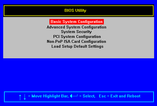
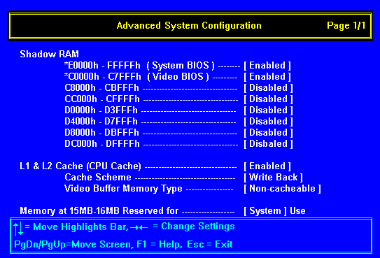
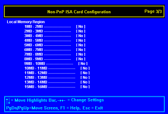
To enter the CMOS Setup screens press CTRL+ALT+ESC after boot-up.
There is no way of draining CMOS on this motherboard. There is an
emergency boot procedure in the event of CMOS corruption. Hold down the F10 key and power
on the machine, a single beep is produced at which time you may release F10.




 
Interrupts, Memory & I/O Ports
I/O Ports
I/O ports (Hex) |
Used by |
000 - 00F |
DMA controller 1 |
020 - 021 |
Interrupt controller 1 |
022 - 023 |
ESC configuration |
040 - 043 |
System timer 1 |
048 - 04B7 |
System timer 2 |
061 |
NMI status and control |
070 |
NMI mask |
080 - 08F |
DMA page register |
0A0 - 0A1 |
Interrupt controller 2 |
0B2 - 0B3 |
Advanced power management |
0C0 - 0DE |
DMA controller 2 |
0F0 |
Reset IRQ 13 |
4F0 |
Special system control port |
400 - 4FF |
DMA |
C00 |
Configuration RAM page regulation |
CF8 |
PCI configuration address regulation |
CFC |
PCI configuration data regulation |
1F0 - 1F7 |
Hard disk |
278 - 27F |
Parallel port 2 |
2F8 - 2FF |
Serial port 2 |
378 - 37F |
Parallel port 1 |
3B0 - 3BF |
Monochrome display |
3C0 - 3CF |
EGA, VGA, SVGA |
3D0 - 3DF |
CGA, VGA, SVGA |
3F0 - 3F7 |
Diskette drive controller |
3F8 - 3FF |
Serial port 1 |
Interrupts (IRQ)
Interrupts |
Default Function |
IRQ 0 |
System timer |
IRQ 1 |
Keyboard |
IRQ 2 |
Reserved |
IRQ 3 |
Serial port 2 |
IRQ 4 |
Serial port 1 |
IRQ 5 |
Reserved |
IRQ 6 |
Diskette controller |
IRQ 7 |
Parallel port |
IRQ 8 |
Real time clock |
IRQ 9 |
Reserved |
IRQ 10 |
Reserved |
IRQ 11 |
Reserved |
IRQ 12 |
Mouse |
IRQ 13 |
Co processor |
IRQ 14 |
Primary IDE interface |
IRQ 15 |
Secondary IDE interface |
Memory Map
| Address Range (hex) |
Size |
Function |
| 0000000 - 009FFFF |
640 KB system memory |
Onboard DRAM |
| 00A0000 - 00BFFFF |
128 KB video RAM |
Graphics display buffer |
| 00C0000 - 00C7FFFF |
32 KB I/O expansion ROM |
Video BIOS |
| 00C800 - 00CFFFF |
32 KB I/O expansion ROM |
Reserved for ROM on I/O adapters |
| 00D0000 - 00DFFFF |
64 KB I/O expansion ROM |
Reserved for ROM on I/O adapters |
| 00E0000 - 00E7FFF |
32 KB for SCSI BIOS |
System extended BIOS (SCSI BOS) |
| 00E8000 - 00E7FFF |
32 KB |
Reserved for system extended BIOS |
| 00F0000 - 00FFFFF |
64 KB BIOS |
System BIOS |
| 0100000 - FFFFFFF |
System Memory |
Onboard DRAM |
 
Rear Panel
Currently not available.
 
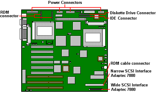
Other Motherboard Connections
 

|


