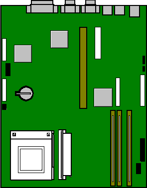
PCL6000 Motherboard (Rev 1.13)

RAM Configuration
DIMM specification
Memory can be fitted in three vertical DIMM sockets which must be
populated with gold contact, 3.3V, 72-bit unbuffered EDO type DIMMs having 60 ns timing.
The three DIMM slots accept DIMMs of 16, 32 and 64 Mbytes in any
combination, to the maximum of 192 Mbytes.
DIMMs are not the same as those used on 'Cosworth' motherboards.
Disk Drives
| MB |
Make |
Model |
Type |
Part Number |
| 2GB |
IBM |
DORS-32160 |
UltraSCSI |
SU58303 |
| 4GB |
IBM |
DCAS-34330 |
UltraSCSI |
XB61177 |
Tape Drives
| MB |
Make |
Model |
Type |
Part Number |
| 12-24GB |
HP |
HP C1537A |
DDS III |
SU61220 |
Floppy Drives
| MB |
Make |
Model |
Type |
Part Number |
| 2 MB |
Mitsubishi |
355F-2450MP |
3.5" |
|
CD-ROM
Ethernet Options
Jumper Settings
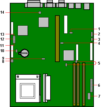
| 1 |
J80 - audio enable/disable |
8 |
PL74 and PL75 - fan connectors |
| 2 |
PL86 - speaker links |
9 |
J70 - Reserved. Do not move. |
| 3 |
J40 - hard disk LED select |
10 |
J72 - battery disconnect |
| 4 |
J71 - Reserved. Do not move |
11 |
J1 to 4 - CPU clock divisor |
| 5 |
J90 and J91 - SCSI setting links |
12 |
J32 - board bus frequency |
| 6 |
PL70 and PL71 - case connections |
13 |
J30 and J31 - BIOS links |
| 7 |
PL20 - front bezel daughterboard |
14 |
J60 - floppy drive setting |
Processor clock multiplier, J1 to 4
| J1 |
J2 |
J3 |
J4 |
Ratio |
| I |
I |
I |
I |
2:1 (2x) |
| I |
I |
O |
I |
3:1 (3x) 200MHz (J32 - No fit) |
| I |
I |
I |
O |
4:1 (4x) |
| I |
I |
O |
O |
5:1 (5x) |
| I |
O |
I |
I |
5/2 (2.5x) 166MHz (J32 - No fit) |
| I |
O |
O |
I |
7/2 (3.5x) |
| I |
O |
I |
O |
9/2 (4.5x) |
| I |
O |
O |
O |
11/2 )5.5x) |
| O |
X |
X |
I |
Strictly reserved |
| O |
O |
O |
O |
2:1 (2x) |
| I=jumper fitted |
O=No jumper |
X=Don’t care |
Bus speed select, J32
| Frequency |
Jumper J32 |
| 60 MHz |
No jumper |
| 66 MHz |
Jumper fitted * |
Flash BIOS, J30 & J31
| Recovery J30 |
Program enable J31 |
| 2-3, Normal * |
1-2, Enable * |
| 1-2, Recover |
2-3, Disable |
Battery backup, J72
| Erase CMOS settings |
| 1-2, Normal * |
| 2-3, >1 sec. to discharge |
Audio disable, J80
| Audio J80 |
| 1-2, Enable Audio |
| 2-3, Disable Audio * |
On-board SCSI Interface, J90 & J91
| Link |
SCSI Enable - J90 |
SCSI Type - J91 |
Link |
| 1 - 2 |
Enable SCSI * |
Non Ultra SCSI |
ON |
| 2 - 3 |
Disable SCSI |
Ultra wide SCSI * |
OFF |
Hard drive LED, J40
| J90 setting (see above) |
Set J40 as follows: |
| SCSI Disabled (IDE drives fitted) |
1 - 2 |
| SCSI Enabled (SCSI drives fitted) |
2 - 3 * |
Floppy Disk mode, J60
| Pins |
Floppy options J60 |
| 1-3 & 2-4 |
3-mode operation |
| 3-4 |
Standard 2-mode drives * |
| |
Software control for 1.2Mb mode operation in Japan |
Speakers, PL86 (if fitted)
| This is only for special system
cases with internal stereo speakers, the normal casing is only fitted with a single
‘beep’ type speaker, connected to PL71. |
| Pins |
Function |
Connection PL86 |
| 1 |
Stereo - Left |
Left speaker = pins 1 and 2 |
| 2 |
Audio ground |
|
| 3 |
Mono |
Mono = pins 3 and 2 |
| 4 |
Link |
Link 4 and 5 for mono |
| 5 |
Stereo - Right |
Right speaker = pins 5 and 6 |
| 6 |
Audio ground |
|
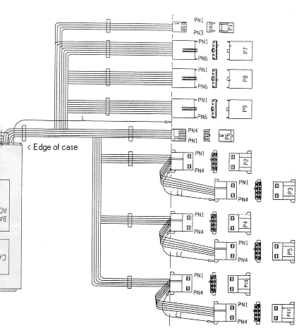
Fan Connectors, PL73 & PL74
| Pins |
CPU Fansink PL73 |
Pins |
Main fan PL74 |
| 1 |
Ground |
1 |
Ground |
| 2 |
Fan Fail |
2 |
Controlled supply |
| 3 |
+ 12 volts |
3 |
Ground |
Front and panel connectors, PL70 & PL71
| Row A - PL70 |
Pins |
Row B - PL71 |
| Power (PSU control) |
1 |
Standby switch |
| Power return |
2 |
Standby switch return |
| (Connected to pin 6) |
3 |
Vcc |
| Keyed |
4 |
Keyed |
| Hard disk LED signal |
5 |
IRDA input |
| Hard disk LED pullup |
6 |
Ground |
| Ground |
7 |
IRDA output |
| Keylock switch |
8 |
Ground |
| Keylock switch return |
9 |
Not used |
| Power on LED signal |
10 |
Not used |
| Power on LED return |
11 |
Speaker out (BEEP) |
| Standby LED signal |
12 |
Message LED signal |
| Standby LED return |
13 |
Message LED pullup |
| Reset switch return |
14 |
Not used |
| Reset switch |
15 |
Not used |
Front panel connector, PL20
| Analogue ground |
1 |
2 |
KEYED |
| No connection |
3 |
4 |
No connection |
| No connection |
5 |
6 |
No connection |
| Message LED (control 2) |
7 |
8 |
No connection |
| Message LED (control 1) |
9 |
10 |
5 V supply (fused) |
| IR transmit |
11 |
12 |
RTS |
| IR receive |
13 |
14 |
Digital ground |
* - Default
Additional Options
Server Products
Desktop Products
| Modems |
|
| V32 data/fax/voice modem.
|
XB55987 |
| V34 data/fax/voice modem.
|
XB57689 |
| Video Memory |
|
| 1MB to 2MB EDO DRAM Upgrade |
XB57374 |
| Graphics Cards |
|
| Matrox MGA Millenium PCI, 4MB WRAM, (See Note below) |
XB57212 |
| SCSI Cards |
|
| SCSI card add-in (No HD Support) |
SA50160 |
| Adaptec 2940 PCI SCSI card |
UD55556 |
| Specialix Serial Cards |
|
| 32-port ISA SI/XIO serial card |
XB54693 |
| 4 port terminal adaptor |
XB43319 |
| 8 port terminal adaptor |
XB43320 |
| 8 port modular terminal adaptor |
XB54611 |
| 8 port modular terminal adaptor (7 RS232, 1 PARALLEL) |
XB54612 |
| Audio Options |
|
| Apricot Deepsound Subwoofer |
XB58090 |
| 20W Powered external speakers |
XB55607 |
| Wave Table Card |
XB57690 |
Rear Panel
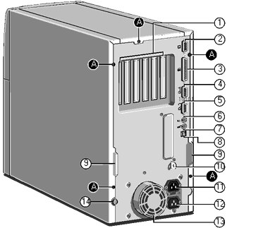
|
| 1 Rear of expansion bay |
9 Handles to assist side panel removal |
| 2 Not fitted on this model *1 |
10 Security loop for cable or padlock |
| 3 Parallel or printer port |
11 AC power output for monitor |
| 4 Serial port 2 |
12 AC power input from supply |
| 5 Serial port 1 |
13 Protection cover for PSU fan *2 |
| 6 PS/2 port for mouse |
14 Main side panel locking |
| 7 PS/2 port for keyboard |
|
| 8 USB port for future use |
A - Panel fixing screws |
| *1 A high grade video board is fitted into one of the PCI
expansion slots |
*2 DO NOT use this to lift the system |
Replacing CMOS Battery
The battery is a 3 volt lithium type (CR2032 or equivalent) typically
used in calculators, watches and other small, battery-powered electronic items. The
average battery life is between 3 and 5 years.
Read carefully the following instructions before commencing work.
1. Turn off the computer and unplug all power cords. Take suitable
anti-static precautions and remove the system unit cover.
2. Identify the battery holder.
3. Carefully disconnect and remove any expansion cards that may obstruct
easy access to the battery. Take note of any cable positions before removal.
Warning
Do not use a metal or other conductive implement to remove the battery.
If a short-circuit is accidentally made between its positive and negative terminals, it
may cause the battery to explode.
4. Lift the edge of the battery far enough to clear the base of the
holder, then slide the battery from under the contact spring.
5. Taking care not to touch the top or bottom surface of the battery,
pick up the replacement with the positive (+) terminal upwards and slide the battery into
the holder from the same side the old battery was removed.
6. Replace any expansion cards you had to remove in step 4 and replace
the system unit cover.
7. Dispose of the old battery according to the makers instructions.
When you next turn on the computer you will have to run the BIOS Set-up
utility to enter the hardware configuration. See ‘System BIOS and set-up’ for
guidance.
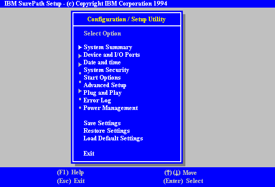
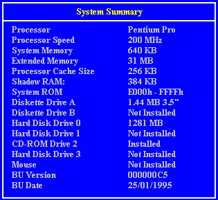
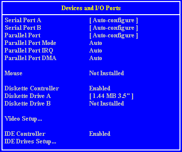
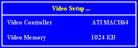
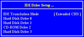
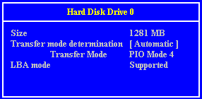
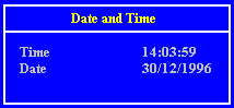
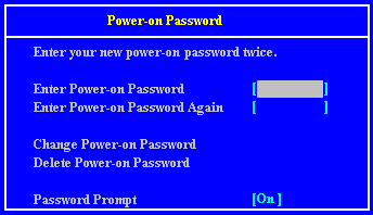
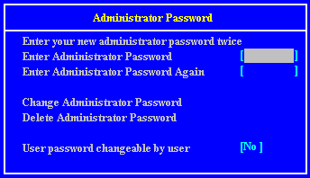
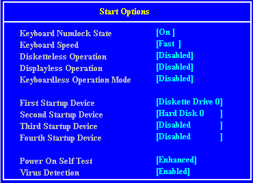
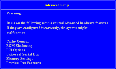
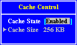
Setup Screens


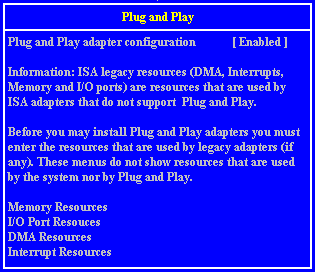
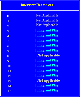
Interrupts (IRQ)
| IRQ |
Default assignment |
Available? |
| IRQ0 |
System timer |
No |
| IRQ1 |
Keyboard controller |
No |
| IRQ2 |
System |
No |
| IRQ3 |
Serial port 2 |
Optionally |
| IRQ4 |
Serial port 1 |
Optionally |
| IRQ5 |
Audio (if fitted) |
Yes |
| IRQ6 |
Diskette controller |
No |
| IRQ7 |
Parallel port |
Optionally |
| IRQ8 |
Real time clock |
No |
| IRQ9 |
|
Yes |
| IRQ10 |
|
Yes |
| IRQ11 |
|
Yes |
| IRQ12 |
Mouse |
No |
| IRQ13 |
Coprocessor |
No |
| IRQ14 |
Primary ATA/IDE interface |
Optionally |
| IRQ15 |
Secondary ATA/IDE interface |
Optionally |
| IRQ3 is available if you disable serial port
2 with the BIOS Setup utility. |
| IRQ4 is available if you disable serial port
1. |
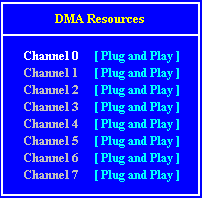
Direct memory access (DMA) channel
| DMA |
Default assignment |
Available? |
| DMA0 |
|
Yes |
| DMA1 |
Default (8 bit) Audio |
Optionally |
| DMA2 |
Diskette/floppy disk controller |
No |
| DMA3 |
Enhanced Capabilities Port (default) |
Optionally |
| DMA4 |
System |
No |
| DMA5 |
Default (16 bit) Audio |
Optionally |
| DMA6 |
|
Yes |
| DMA7 |
|
Yes |
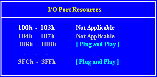
I/O Ports
| I/O ports |
Default assignment |
| 000h-01Fh |
DMA controller 1 |
| 020h-021h |
Interrupt controller 1 |
| 034h, 038h, 03Ch |
Alternate Local bus ATA/IDE |
| 040h-05Fh |
System timer |
| 060h-06Fh |
Keyboard controller |
| 070h-07Fh |
Real-time clock, NMI mask |
| 080h-09Fh |
DMA page register |
| 0A0h-0A1h |
Interrupt controller 2 |
| 0B4h, 0B8h, 0BCh |
Local bus ATA/IDE |
| 0C0h-0DFh |
DMA controller 2 |
| 0F0h, 0F1h |
Math coprocessor busy (clear/reset) |
| 0F8h-0FFh |
Math coprocessor |
| 1F0h-1F7h |
Hard disk drive controller |
| 200h-207h |
Game I/O (disable) |
| 220h-22Fh, 230h-233Fh |
Sound blaster system |
| 240h-24Fh, 250h-253Fh |
Alternate Sound blaster system |
| 278h-27Fh |
Parallel port 2 |
| 2B0h-2DFh |
Alternate VGA |
| 2F8h-2FFh |
Serial port 2 |
| 300h-301Fh |
Alternate MIDI (disable) |
| 330h-331Fh |
MIDI |
| 378h-37Fh |
Parallel port 1 |
| 388h-38Fh |
FM synthesiser |
| 3B0h-3BFh |
Monochrome display and printer adapter |
| 3B4h, 3B5h, 3BAh |
Video subsystem |
| 3C0h-3C5h |
VGA |
| 3C6h-3C9h |
Video DAC |
| 3CAh-3DFh |
VGA |
| 3F0h-3F7h |
Diskette drive controller |
| 3F8h-3FFh |
Serial port 1 |
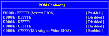
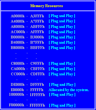
Base memory address
Some expansion cards are fitted with memory of their own, usually
read-only memory (ROM) containing functional extensions to the computer’s BIOS (basic
input/output system) ROM. Some cards also have random-access memory (RAM).
In order that this memory can be recognised by the system processor, it
must be mapped somewhere within the computer’s own address space. By setting the base
memory address you specify where the card’s memory begins within the address space.
Typically, an expansion card’s memory must be mapped onto the addresses between
C8000h and DFFFF in upper memory. With most modern expansion cards this is fully
automatic.
The card’s documentation should list its possible base memory
addresses. You will also need to know how much memory the card has, so that you can leave
the right gap between this card’s base address and the next.
Cards often come with pre-configured or default settings. It is best to
rely on these settings as much as possible, and change them only if they conflict with
other devices.
Beep codes
No beeps. If no beeps are heard at all the speaker may
be disconnected or there may be a speaker circuitry fault.
One short beep. Marks the completion of POST and no
functional errors found. You will also get a single beep if you press an invalid key for a
power-on password.
Two short beeps. Indicates and draws your attention to
an error during POST. This should be accompanied by an error message.
Three short beeps. System memory error, normally
accompanied by code 201. Beeps are used when the video cannot display the code.
Continuous beep. Could indicate a serious failure of
the system motherboard, or a failure of the speaker circuitry.
Repeating short beeps. Usually indicative of a keyboard
key stuck down, but may be due to the keyboard interface failing.
One long and one short beep. POST has detected an error
on the video adapter in the system. There may be no display on the screen.
One long and two short beeps. This means that either
the video system is faulty, or that a video I/O adapter ROM is not readable.
Two long and two short beeps. The video subsystem
cannot be supported by the main system POST. This can occur when the video subsystem is
replaced or changed on site.
Many of these following codes indicate a serious fault and the system
may halt. Switch off for 20 to 30 seconds and try again. If the fault persists, make a
note of it and call your maintenance provider.
| Number of beeps |
Meaning |
| 1-1-3 |
CMOS write/read test failure |
| 1-1-4 |
BIOS ROM checksum failure |
| 1-2-1 |
Programmable Interval Timer test failure |
| 1-2-2 |
DMA initialisation failure |
| 1-2-3 |
DMA page register read/write test failure |
| 1-2-4 |
RAM refresh verification failure |
| 1-3-1 |
First 64K RAM test failure |
| 1-3-2 |
First 64K RAM parity test failure |
| 1-3-3 |
Slave DMA register test failure |
| 1-3-4 |
Master DMA register test failure |
| 1-4-1 |
Master interrupt mask register test failure |
| 1-4-2 |
Slave interrupt mask register test failure |
| 1-4-4 |
Keyboard controller test failure |
| 2-2-2 |
Search for video ROM test failure |
| 2-2-3 |
Screen believed inoperable |
| 2-2-4 |
Timer tick interrupt test failure |
| 2-3-1 |
Interval timer channel 2 test failure |
| 2-3-3 |
Time-of -day clock test failure |
| 2-4-3 |
CMOS memory size against actual compare failure |
| 2-4-4 |
Memory size mismatch occurred |
Error Messages
If you get an error which is not listed or the problem persists, call
your maintenance provider.
| Code |
Cause |
Code |
Cause |
| 0 |
Keyboard locked |
301 |
Keyboard clock line failure |
| 062 |
Boot failure. Default values loaded |
301 |
Keyboard data line failure |
| 101 |
Timer tick interrupt failure |
301 |
Keyboard stuck key failure |
| 102 |
Timer 2 test failure |
303 |
Keyboard controller failure |
| 106 |
Diskette controller failure |
604 |
Diskette drive 0 failure |
| 110 |
System board memory parity interrupt |
604 |
Diskette drive 1 failure |
| 114 |
Option ROM checksum failure |
605 |
Diskette unlocked problem |
| 151 |
Real time clock failure |
662 |
Diskette drive configuration |
| 161 |
Real time clock battery failure |
762 |
Coprocessor configuration |
| 162 |
CMOS RAM checksum failure |
962 |
Parallel configuration |
| 162 |
Invalid configuration information |
1162 |
Serial configuration |
| 163 |
Time of day not set -preboot |
1762 |
Hard disk configuration |
| 164 |
Memory size does not match CMOS |
1780 |
Fixed disk 0 failure |
| 165 |
Add/remove MC card |
1781 |
Fixed disk 1 failure |
| 166 |
Memory configuration change |
1782 |
Fixed disk 2 failure |
| 175 |
Bad EEPROM CRC #1 |
1783 |
Fixed disk 3 failure |
| 176 |
System tampered |
1800 |
No more IRQ available |
| 177 |
Bad PAP checksum |
1801 |
No more room for option ROM |
| 178 |
EEPROM is not functional |
1802 |
No more I/O space available |
| 183 |
PAP update required |
1803 |
No more memory <1Mb available |
| 184 |
Bad POP checksum |
1804 |
No more memory >1MB available |
| 185 |
Corrupted Boot sequence |
1805 |
Checksum error or 0 size option ROM |
| 186 |
Hardware problem |
1806 |
PCI-PCI bridge error |
| 187 |
VPD S/N not set |
1962 |
No bootable device |
| 188 |
Bad EEPROM CRC #2 |
2400 |
Display adapter failed ; using alternate |
| 189 |
Excessive password attempts |
2462 |
Video configuration |
| 201 |
Base memory error |
5962 |
IDE CD-ROM configuration |
| 229 |
External cache failure |
8601 |
Pointer device failure |
| 301 |
Keyboard failure |
8603 |
Pointer device has been removed |
PSU Wiring
The psu should be tested to conform to the design specification
parameters set out in the Design Specification :-
Regulation
| Parameter |
Current Range |
Range |
Minimum |
Nominal |
Maximum |
| +12v DC |
0.0A to 10.0A |
+12v ±5% |
+11.40v |
+12.00v |
+12.60v |
| +5v DC |
1.5A to 22.0A |
+5v ±5% |
+4.75v |
+5.00v |
+5.25v |
| +3v3 DC |
0.3A to 14.0A |
+3v3 ±5% |
+3.15v |
+3.30v |
+3.45v |
| -5v DC |
0.0A to 0.5A |
-5v ±10% |
-4.50v |
-5.00v |
-5.50v |
| -12v DC |
0.0A to 0.8A |
-12v ±10% |
-10.80v |
-12.00v |
-13.20v |
Power Good Signal
At Power Up:
Power good should go valid within 100mS and 500mS of the +5V signal
reaching 4.75V
At Power Down:
Power good should go fails at least 1mS before the +5V signal goes below
the regulation limits

|