 |


|
|
'Diamond' Motherboard
(Rev 1.9.1)
Cache SIMM Socket
If you have a 75MHz motherboard it will not have a cache SIMM, due
to the performance benefits of EDO RAM. If however you upgrade the processor at a later
date you may require a cache upgrade to improve performance by even more.
The part numbers for the Cache SIMMs available are as follows:
PT12356130 IC - SIMM 256KB ASYNC CACHE MODULE
PT12361431 CACHE - 256KB 55MHz PIPELINED SYNC
See also - Spares News /
Product Update - NL0032
 
RAM Configuration
The SIMM sockets are located at the front of the motherboard. Each pair
of sockets can be fitted with SIMMs. SIMMs with capacities of 2, 4, 8, 16 or 32 Mbytes are
supported, giving a maximum capacity of 128 Mbytes.
Socket Location
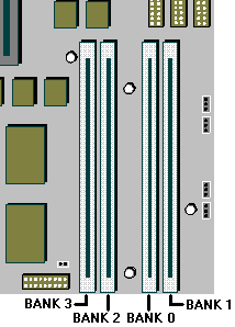
SIMMs must be fitted in pairs and the pair must be identical. The system
does not require Parity checking (36-bit) SIMMs. Conventional 32-bit SIMMs with a refresh
rate of 70ns is the specification. The newer Extended Data Output (EDO) type SIMMs are
supported and will give enhanced performance.
Possible SIMM Memory Combinations
Total Memory |
Bank 0 |
Bank 1 |
Bank 2 |
Bank 3 |
8 Mb |
4 Mb |
4 Mb |
- |
- |
12 Mb |
4 Mb |
4 Mb |
2 Mb |
2 Mb |
16 Mb |
4 Mb |
4 Mb |
4 Mb |
4 Mb |
16 Mb |
8 Mb |
8 Mb |
- |
- |
20 Mb |
8 Mb |
8 Mb |
2 Mb |
2 Mb |
24 Mb |
8 Mb |
8 Mb |
4 Mb |
4 Mb |
32 Mb |
8 Mb |
8 Mb |
8 Mb |
8 Mb |
32 Mb |
16 Mb |
16 Mb |
- |
- |
36 Mb |
16 Mb |
16 Mb |
2 Mb |
2 Mb |
40 Mb |
16 Mb |
16 Mb |
4 Mb |
4 Mb |
48 Mb |
16 Mb |
16 Mb |
8 Mb |
8 Mb |
64 Mb |
16 Mb |
16 Mb |
16 Mb |
16 Mb |
64 Mb |
32 Mb |
32 Mb |
- |
- |
68 Mb |
32 Mb |
32 Mb |
2 Mb |
2 Mb |
72 Mb |
32 Mb |
32 Mb |
4 Mb |
4 Mb |
80 Mb |
32 Mb |
32 Mb |
8 Mb |
8 Mb |
96 Mb |
32 Mb |
32 Mb |
16 Mb |
16 Mb |
128 Mb |
32 Mb |
32 Mb |
32 Mb |
32 Mb |
Note: MS530 has only Banks 0 & 1 available
for memory expansion. |
 
Ethernet Options
| 3Com triple-combo (thin/thick/UTP) Ethernet card, (3C509B) |
XB55742 |
| 3Com 10/100 PCI (3C595TX) |
XB54991 |
 
Disk Drives
Hard Disks
Tape Drives
| MB |
Make |
Model |
Type |
Part Number |
| 400 - 800MB |
Conner |
CTT800R-F |
Floppy |
XB56352 |
| 4-16 GB |
Conner |
CTD8000R-S |
DDS II SCSI |
SU54778 |
| 1.6-3.2 GB |
Conner |
CTM3200R-S |
SCSI |
XB54027 |
Floppy Drives
| MB |
Make |
Model |
Type |
Part Number |
| 2 MB |
Mitsubishi |
355F |
3.5" |
|
| 2 MB |
Mitsubishi |
355F-2450MP |
3.5" |
|
CD-ROM Drives
 
Jumper Settings
Internal speaker operation
Next to outer SIMM socket, default position link pins 4 and 5 gives
audio output to the internal speaker in mono. Only to be removed in a system having
internal stereo speakers.
| PL2 |
Stereo: L Cable = 1, 2 R Cable = 5, 6. |
| |
Mono: Cable = 2, 3. Jumper = 4, 5. |
Internal 'audio' modem
Just along from the CD audio connection, default position if no internal
modem is fitted, link pins 3 and 4. Remove only when fitting an internal modem supporting
sound.
| PL4 |
Modem absent = 3, 4. |
| |
Modem present = no jumper |
BIOS reprogramme
These links are for special purposes. Only to be used for an official
upgrade to the system BIOS. DO NOT move for any other reason.
| PL5 |
Reserved. Do not change from 2, 3. |
| PL6 |
Flash Program. |
| |
Enable = 1, 2. Disable = 2, 3. |
Floppy disk control mode
Next to floppy disk ribbon connector, default position
link pins 3 and 4.
| PL13 |
2 mode =  |
| |
3 mode =  |
Clear BIOS settings
Next to outer video upgrade socket, default position linkpins 1 and 2.
Moving the link to pins 2 and 3 disconnects the battery from the BIOS memory, and will
cause all the user settings to be lost. To be used with caution and only in the event of
an access password being lost.
| PL21 |
Normal = 1, 2. Clear = 2, 3. |
Video / VESA option
A single jumper may be the only one fitted, at the end nearest PL21.
Only needs to be removed if fitting a new high feature 'plug-in' video card and serious
problems are encountered. If taken out, it must be replaced if the extra video card is
subsequently removed.
| PL22 |
Video enabled, do not alter. |
Processor and BUS clock
These settings MUST NOT be changed except in the event of a processor
upgrade. Full details of the processors required settings should accompany the new
processor and the apropriate board links should then be identified from the table below.
Warning
DO NOT alter these links under normal circumstances as it could lead to
the destruction of the processor and/or other vital components on the board
| Processor Speed |
PL17 |
SW1, || = Link, : = No link |
ISA (MHz) |
| Pentium P 75 |
VRE |
Pin 1 || || : : : : : : |
8.33 |
| P 90 |
VRE |
Pin 1 : || : : || : : : |
7.5 |
| P 100 |
VRE |
Pin 1 || : : : || : : : |
8.33 |
| P 120 |
VRE |
Pin 1 : || || : || : : : |
7.5 |
| P 133 |
VRE |
Pin 1 || : || : || : : : |
8.33 |
| P 150 |
VRE |
Pin 1 : || || || || : : : |
7.5 |
| P 166 |
VRE |
Pin 1 || : || || || : : : |
8.33 |
| P 200 |
VRE |
Pin 1 || : : || || : : : |
8.33 (5-07 BIOS or greater Ref IPB4172) |
Soundblaster Address
| IC12 |
Near CD audio connector. Default position, link rear pins, sets the
on-board Soundblaster to address 220h. Removing the link changes the address to 240h |
PL24, PL28
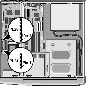
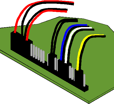
This range of pins is not exactly for jumpers, but is used
to connect various features around the system case to the motherboard.
PL24, PL28 Pinouts
| PL24 |
Pins |
1 to 4 |
HDD active light |
| |
|
5 to 9 |
Keylock (not fitted) |
| |
|
10 & 11 |
System in 'power standby' light |
| |
|
12 & 13 |
System hardware reset (not fitted) |
| PL28 |
Pins |
1 & 2 |
System standby restore switch |
| |
|
3 to 7 |
Infrared controller |
| |
|
8,9,10 |
Fan, slow mode |
| |
|
11,12,13 |
Fan, full speed mode |
| |
|
14 to 17 |
Internal speaker ( only when no audio fitted to motherboard) |
 
Additional Options
| Modems |
|
|
Voice/Data
modem |
| Add-in Cards |
|
|
Hauppage TV Card |
|
Radio Card |
|
Matrox MGA Millenium PCI, 2MB WRAM, XB57211 (See Note
below) |
|
Matrox MGA Millenium PCI, 4MB WRAM, XB57212 (See Note
below) |
|
SCSI card add-in (No HD Support) SA50160 |
|
Adaptec 2940 PCI SCSI card UD55556 |
|
Wave Table
Card |
| Video Memory |
|
|
GD5434 1MB to 2MB Video RAM XB54893 |
|
GD5436 1MB to 2MB Video RAM XB57374 |
 
Rear Panel
 
Expansion Slots
 
CMOS Discharge
To discharge CMOS refer to jumper Clear BIOS settings PL21 (see below)

Clear BIOS settings
Next to outer video upgrade socket, default position linkpins 1 and 2.
Moving the link to pins 2 and 3 disconnects the battery from the BIOS
memory, and will cause all the user settings to be lost. To be used with caution and only
in the event of an access password being lost.
PL21 Normal = 1, 2. Clear = 2, 3.
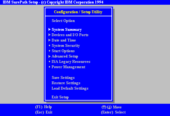
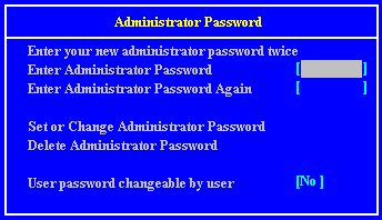
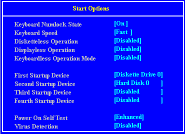
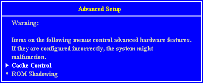
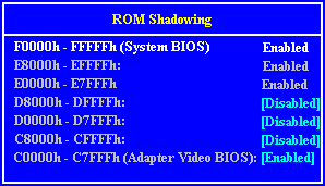
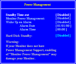
When this appears in the top right of the screen press the
F1 on the keyboard and in a few seconds you will be presented with the BIOS setup screen
(see below)
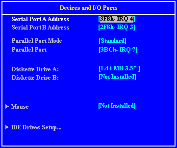
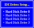
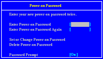
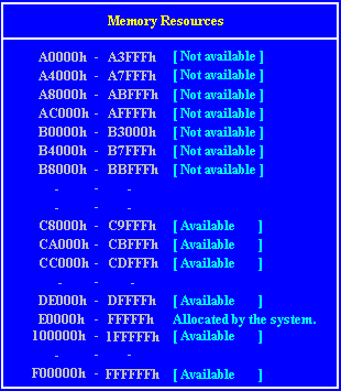
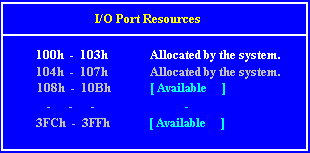
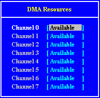
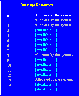
Configuration / Setup Utility







Interrupts, Memory & I/O Ports
Interrupts (IRQ)
Interrupts |
Default Function |
Available ? |
IRQ 0 |
System timer |
No |
IRQ 1 |
Keyboard |
No |
IRQ 2 |
Cascade |
No |
IRQ 3 |
Serial port 2 |
Optionally |
IRQ 4 |
Serial port 1 |
Optionally |
IRQ 5 |
Audio (if fitted) |
Yes |
IRQ 6 |
Diskette controller |
No |
IRQ 7 |
Parallel port |
Optionally |
IRQ 8 |
Real time clock |
No |
IRQ 9 |
Not used |
Yes |
IRQ 10 |
Not used |
Yes |
IRQ 11 |
Not used |
Yes |
IRQ 12 |
Mouse |
No |
IRQ 13 |
Co processor |
No |
IRQ 14 |
Primary ATA/IDE interface |
No |
IRQ 15 |
Secondary ATA/IDE
interface |
No |
I/O Ports
I/O ports (Hex) |
Used by |
000 - 01F |
DMA controller 1 |
020 - 021 |
Interrupt controller 1 |
022 - 023 |
ALI configuration port |
034, 038, 03C |
Local bus ATA/IDE (alternate) |
040 - 05F |
System timer |
060 - 06F |
Keyboard controller |
070 - 07F |
Real time clock,NMI mask |
080 - 09F |
DMA page register |
0A0 - 0A1 |
Interrupt controller 2 |
0B4, 0B8, 0BC |
Local bus ATA/IDE (default) |
0C0 - 0DF |
DMA controller 2 |
0F0, 0F1 |
Math coprocessor busy (clear/reset) |
0F8 - 0FF |
Math coprocessor |
1F0 - 1F7 |
Hard disk drive controller |
200 - 207 |
Game I/O |
278 - 27F |
Parallel port 2 |
2B0 - 2DF |
Alternate VGA |
2F8 - 2FF |
Serial port 2 |
378 - 37F |
Parallel port 1 |
3B0 - 3BF |
Monochrome display and printer adapter |
3B4, 3B5, 3BA |
Video subsystem |
3C0 - 3C5 |
VGA |
3C6 - 3C9 |
Video DAC |
3CA - 3DF |
VGA |
3F0 - 3F7 |
Diskette drive controller |
3F8 - 3FF |
Serial port 1 |
Direct memory access (DMA) channel
DMA |
Default Function |
Available ? |
DMA 0 |
|
Yes |
DMA 1 |
8-bit Audio |
Optionally |
DMA 2 |
Diskette Controller |
No |
DMA 3 |
Enhanced Capabilities Port |
Optionally |
DMA 4 |
System |
No |
DMA 5 |
16-bit Audio |
Optionally |
DMA 6 |
|
Yes |
DMA 7 |
|
Yes |
 
LED Cable Connections
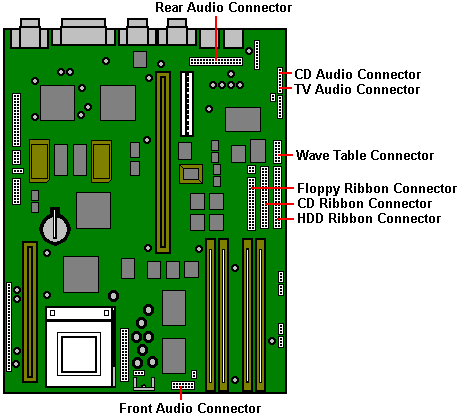
Other Motherboard Connections
 

|


