 |


|
|
'Trent' Motherboard (Rev 1.12.1)
RAM Configuration
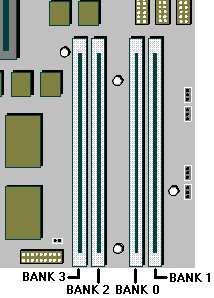
The SIMM sockets are located at the front of the motherboard. Each pair
of sockets can be fitted with SIMMs. SIMMs with capacities of 2, 4, 8, 16 or 32 Mbytes are
supported, giving a maximum capacity of 128 Mbytes.
SIMMs must be fitted in pairs and the pair must be identical. The system
does not require Parity checking (36-bit) SIMMs. Conventional 32-bit SIMMs with a refresh
rate of 60ns is the specification. The newer Extended Data Output (EDO) type SIMMs are
supported and will give enhanced performance.
Possible SIMM Memory Combinations
|
Bank
1 sockets |
Bank
2 sockets |
Total Memory |
MM1 |
MM2 |
MM3 |
MM4 |
8 Mb |
4 Mb |
4 Mb |
- |
- |
12 Mb |
4 Mb |
4 Mb |
2 Mb |
2 Mb |
16 Mb |
4 Mb |
4 Mb |
4 Mb |
4 Mb |
16 Mb |
8 Mb |
8 Mb |
- |
- |
20 Mb |
8 Mb |
8 Mb |
2 Mb |
2 Mb |
24 Mb |
8 Mb |
8 Mb |
4 Mb |
4 Mb |
32 Mb |
16 Mb |
16 Mb |
- |
- |
36 Mb |
16 Mb |
16 Mb |
2 Mb |
2 Mb |
40 Mb |
16 Mb |
16 Mb |
4 Mb |
4 Mb |
48 Mb |
16 Mb |
16 Mb |
8 Mb |
8 Mb |
64 Mb |
16 Mb |
16 Mb |
16 Mb |
16 Mb |
64 Mb |
32 Mb |
32 Mb |
- |
- |
68 Mb |
32 Mb |
32 Mb |
2 Mb |
2 Mb |
72 Mb |
32 Mb |
32 Mb |
4 Mb |
4 Mb |
80 Mb |
32 Mb |
32 Mb |
8 Mb |
8 Mb |
96 Mb |
32 Mb |
32 Mb |
16 Mb |
16 Mb |
128 Mb |
32 Mb |
32 Mb |
32 Mb |
32 Mb |
Socket Location
 
Ethernet Options
| 3Com triple-combo (thin/thick/UTP) Ethernet
card, (3C509B) |
XB55742 |
| 3Com 10/100 PCI (3C595TX) |
XB54991 |
 
Disk Drives
Hard Disks
| MB |
Make |
Model |
Type |
Part Number |
| 1280 |
Quantum |
TM1280A |
IDE |
SU59082 |
| 1280 |
Quantum |
BF1275A |
IDE |
XB59143 |
| 2100 |
Quantum |
TM2110A |
IDE |
SU59083 |
| 2550 |
Quantum |
BF2550A |
IDE |
XB59144 |
| 3200 |
Quantum |
TM3200A |
IDE |
SU59084 |
Tape Drives
| MB |
Make |
Model |
Type |
Part Number |
| 400-800 |
Conner |
CTT800R-F |
Floppy |
XB56352 |
| 1.6-3.2GB |
Conner |
CTM3200R-S |
SCSI |
XB54027 |
| 4-16GB |
Conner |
CTD8000R-S |
SCSI |
SU54778 |
Floppy Drives
| MB |
Make |
Model |
Type |
Part Number |
| 2 MB |
Mitsubishi |
355F-2450MP |
3.5" |
|
CD-ROM Drives
| MB |
Make |
Model |
Type |
Part Number |
|
Sony |
CDU511-10/10 |
IDE PCAV |
XB61060 |
|
Sony |
CDU311-10/10 |
IDE |
SU58747 |
| 650 |
Panasonic |
LF1195B |
IDE |
XB59792 |
 
Jumper Settings
PL8 Clearing CMOS
| 1 - 2 |
CMOS Battery connected (default) |
| 2 - 3 |
CMOS battery disconnected |
PL10 BIOS image selection
| 1 - 2 |
Boot using normal BIOS (default) |
| 2 - 3 |
Boot using recovery BIOS |
PL11 BIOS reprogram
| 1 - 2 |
Enabled (default) |
| 2 - 3 |
Disabled |
Floppy disk control mode
| PL22 |
Default position link pins 3 - 4. To enable 3-mode operation of the
drive (not usual in Europe), link 1 - 3, and 2 - 4. |
System Fan
| PL36 |
System fan, slow mode. |
| PL37 |
System fan, full speed mode. |
Soundblaster enable
| PL100 |
Near CD audio connector. Link pins 1 - 2 (default) |
Onboard Video enable
Jumper Block PL32, jumper pair marked 'VGA' |
Link pins to enable onboard Video (default) |
Processor and BUS clock
These settings must not be changed except in the event of a processor
upgrade. Full details of the processor's required settings should accompany the new
processor and the appropriate board links should then be identified from the table below.
Warning
Do not alter these links under normal circumstances as it could lead to
the destruction of the processor and/or other vital components on the board.
| Processor Speed |
Jumper Block PL32 |
| |
BF0 |
BF1 |
FS1 |
FS0 |
ISA |
| Pentium 100 MHz |
2 - 4 |
1 - 3 |
7 - 8 |
|
11 - 12 |
| Pentium 120 MHz |
4 - 6 |
1 - 3 |
|
9 - 10 |
11 - 12 |
| Pentium 133 MHz |
4 - 6 |
1 - 3 |
7 - 8 |
|
11 - 12 |
| Pentium 150 MHz |
4 - 6 |
3 - 5 |
|
9 - 10 |
11 - 12 |
| Pentium 166 MHz |
4 - 6 |
3 - 5 |
7 - 8 |
|
11 - 12 |
| Pentium 200 MHz |
2 - 4 |
3 - 5 |
7 - 8 |
|
11 - 12 |
System Connectors
| PL2 |
1 - 2 |
Left stereo speaker |
| |
5 - 6 |
Right stereo speaker |
| PL4 |
1 - 2 |
System standby restore switch |
| |
3 - 7 |
Infra-red controller |
| |
8 - 11 |
Mono speaker |
| |
12 - 13 |
Message LED |
| PL6 |
1 - 4 |
HDD active light |
| |
5 - 9 |
Keylock (not fitted) |
| |
10 - 11 |
System in 'power standby' light |
| |
12 - 13 |
System hardware reset (not fitted) |
 
Additional Options
| EDO memory expansion |
|
8MB SIMMs (32-bit, 2x4MB) |
XB55966 |
|
16MB SIMMs (32-bit, 2x8MB) |
XB55967 |
|
32MB SIMMs (32-bit, 2x16MB) |
XB55968 |
|
64MB SIMMs (32-bit, 2x32MB) |
XB56999 |
| Modems |
|
|
|
V32 data/fax/voice modem.
|
XB55987 |
|
V34 data/fax/voice modem.
|
XB57689 |
| Video Memory |
|
|
|
1MB to 2MB EDO DRAM Upgrade |
XB57374 |
| Graphics Cards |
|
|
|
Matrox MGA Millenium PCI, 4MB WRAM, (See Note below) |
XB57212 |
| SCSI Cards |
|
|
|
SCSI card add-in (No HD Support) |
SA50160 |
|
Adaptec 2940 PCI SCSI card |
UD55556 |
| Specialix Serial Cards |
|
32-port ISA SI/XIO serial card |
XB54693 |
|
4 port terminal adaptor |
XB43319 |
|
8 port terminal adaptor |
XB43320 |
|
8 port modular terminal adaptor |
XB54611 |
|
8 port modular terminal adaptor (7 RS232, 1 PARALLEL) |
XB54612 |
| Audio Options |
|
|
|
Apricot Deepsound Subwoofer |
XB58090 |
|
20W Powered external speakers |
XB55607 |
|
Wave Table Card |
XB57690 |
 
Rear Panel

 
CMOS Discharge
| PL8 |
Clearing CMOS |
| 1 - 2 |
CMOS Battery connected (default) |
| 2 - 3 |
CMOS battery disconnected |
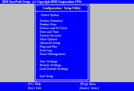
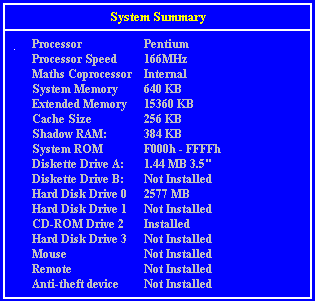
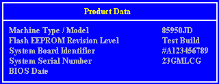
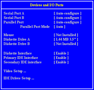
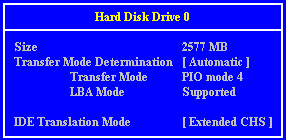
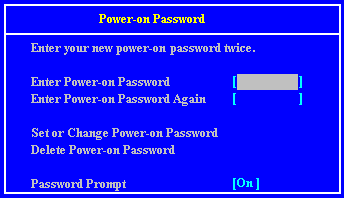
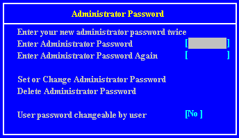
To enter the CMOS Setup screens press F1 setup during
POST.
 




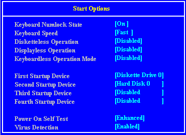


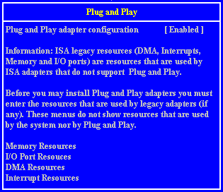


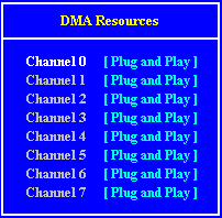
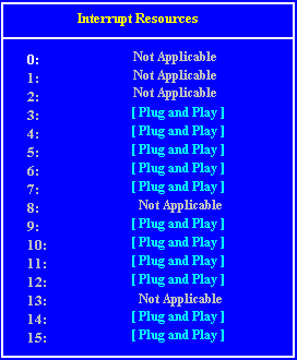


Interrupts, Memory & I/O Ports
I/O Ports
I/O ports (Hex) |
Used by |
000 - 01F |
DMA controller 1 |
020 - 021 |
Interrupt controller 1 |
022 - 023 |
ALI configuration port |
034, 038, 03C |
Local bus ATA/IDE (alternate) |
040 - 05F |
System timer |
060 - 06F |
Keyboard controller |
070 - 07F |
Real time clock,NMI mask |
080 - 09F |
DMA page register |
0A0 - 0A1 |
Interrupt controller 2 |
0B4, 0B8, 0BC |
Local bus ATA/IDE (default) |
0C0 - 0DF |
DMA controller 2 |
0F0, 0F1 |
Math coprocessor busy (clear/reset) |
0F8 - 0FF |
Math coprocessor |
1F0 - 1F7 |
Hard disk drive controller |
200 - 207 |
Game I/O |
220 - 22F, 230 - 233 |
Sound blaster system |
240 - 24F, 250 - 253 |
Alternate Sound blaster system |
278 - 27F |
Parallel port 2 |
2B0 - 2DF |
Alternate VGA |
2F8 - 2FF |
Serial port 2 |
300 - 301 |
Alternate MIDI (disable) |
330 - 331 |
MIDI |
378 - 37F |
Parallel port 1 |
388 - 38F |
FM synthesiser |
3B0 - 3BF |
Monochrome display and printer adapter |
3B4, 3B5, 3BA |
Video subsystem |
3C0 - 3C5 |
VGA |
3C6 - 3C9 |
Video DAC |
3CA - 3DF |
VGA |
3F0 - 3F7 |
Diskette drive controller |
3F8 - 3FF |
Serial port 1 |
 
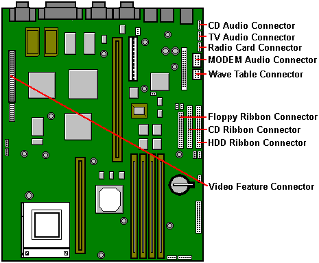
Other Motherboard Connections
 

|


