Revision 'F' LANstation
See Also
IPB 4022 - IPB 4027 - IPB 4033 - IPB 4044
IPB 4046 - IPB 4060 - IPB 4066 - IPB 4100
With the introduction of the new Token Ring LANstation, the motherboard
revision level will move to 'F' and the power supply rating will be upgraded to 40 Watts.
Externally there is little difference but internally some changes to working practice may
be required.
The power supply top cover has been extended to cover the hard disk
drive bay. In order to gain access to the hard disk drive the PSU cover must be removed
exposing the high voltage sections of the supply. Always disconnect the mains supply
before removing the power supply and hard disk cover. Do not test a hard disk drive with
the power supply and hard disk cover removed.
The standard motherboard does not now have a resident network adapter.
All network interface modules are installed by selecting the appropriate daughterboard.
The four interface modules are :-
| Token Ring |
Available Now |
| Unshielded Twisted Pair |
Available Q1 1992 |
| Thin Wire Ethernet |
Available Q1 1992 |
| Thick Wire Ethernet |
Available Q1 1992 |
The Token Ring adapter supports a ring data rate of
either 16 Mbits/s or 4Mbits/s. The rate is set by a switch on the adapter daughterboard.
The default setting is 16Mbits/s. If you need the 4 Mbits/s setting (for example, if your
network includes unshielded cable), move the red switch marked SW1 on the adapter
daughterboard to the front on the machine.
The adapter supports either a 16-bit or 8-bit adapter-to-processor
interface width. The interface width is selectable by means of the SETUP diskette
supplied. The owner's handbook states (on page B/12) that the default width is 16-bit. In
fact the default width is 8-bit, which is the setting that must be used when running IBM
network software (for example, the IBM LAN Support Program).
If the 16-bit setting is used with IBM's DXMCOMOS.SYS IEEE 802.3 driver,
the following error message appears :-
| DXMCO 10E: |
Invalid shared ram address |
|
Error in loading - Press F1 to continue |
The 16-bit interface width can and should be used with
none-IBM software such as Novell NetWare or Microsoft LAN Manager, as this gives
noticeably better performance.
The revision 'F' motherboard will be available in 16MHz and 20MHz
variants. 16MHz versions will have base memory of 1MB, while 20MHz versions will have base
memory of 2MB. In order to cater for the differences in base memory, when adding extra
RAM, a new 2MB and 4MB memory daughter-board has been introduced. The choice of memory
module will depend on how much motherboard memory you start with. The following table
shows the total amount of memory attained using various memory modules:
| Memory Modules |
LANstation Rev 'F' |
LANstation Rev 'F' |
| Available |
386SX-16 (1MByte) |
386SX-20 (2MByte) |
| 1 MByte Module |
2 MBytes |
--- |
| 2 MByte Module |
3 MBytes |
4 MBytes |
| 4 MByte Module |
5 MBytes |
6 MBytes |
| 6 MByte Module |
--- |
8 MBytes |
| 8 MByte Module |
8 MBytes |
8 MBytes |
If your computer already has a memory module installed,
but has not reached the maximum capacity of 8MBytes, you can remove the existing memory
module and replace it with one of a higher capacity. Note that whenever you add a module
which raise total memory above 8MBytes, the memory in excess of 8MBytes is unusable.
The new 2 MByte and 4 MByte modules have a row of three switches along
one edge (1 MByte, 6 MByte and 8 MByte modules do not have switches). The correct position
of these switches depends on the LANstation model you have.
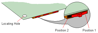
If you have a LANstation 386SX-16 (1MByte base memory) all three
switches must be in position 1 (that is, to the right as viewed with the switches towards
you); if you have a LANstation 386SX-20 (2MByte base memory), the switches must be in
position 2 (to the left). |
